Service Parts Disassembly
Phaser 7100 Service Manual Xerox Internal Use Only4-6
Overview
This chapter contains the removal procedures for field-replaceable parts listed in Chapter 5, Parts List.
In most cases, the replacement procedure is simply the reverse of the removal procedure.
In some instances, additional steps are necessary and are provided for replacement of the parts. For
specific assemblies and parts, refer to the Parts List on page 5-1.
Note: Always use the correct type and size screw (see Fastener Types on page 4-8). Using the
wrong screw can damage tapped holes. Do not use excessive force to remove or install either a
screw or a printer part.
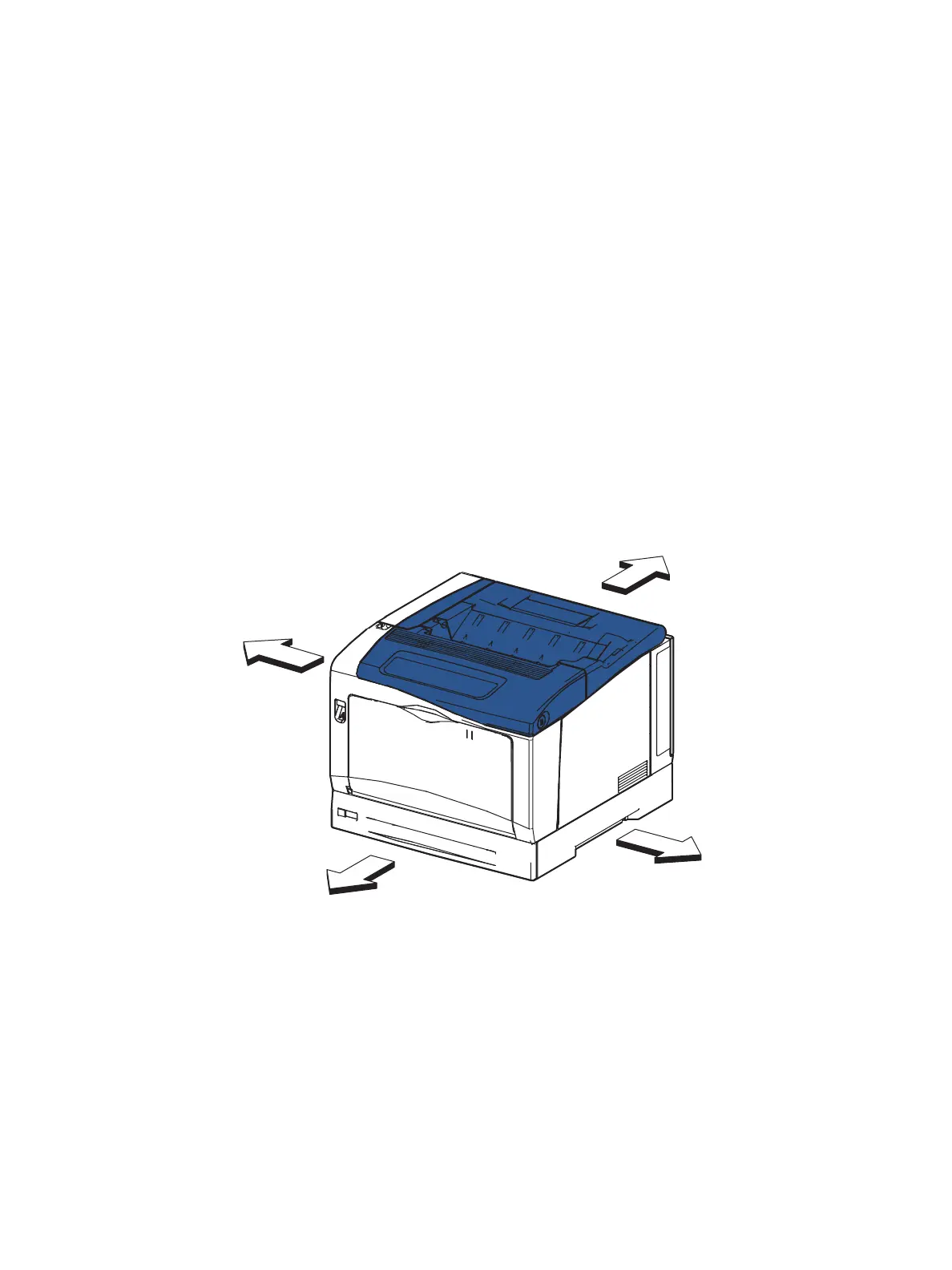
Standard Orientation of the Printer
When needed, printer orientation is called out in the procedure as an aid to locating parts. Figure 1
illustrates the right, left, front, and rear sides of the printer.
Figure 1
s7100-037
Left
Right
Rear
Front

 Loading...


