General and Operation Overview
Xerox Internal Use Only Phaser 7100 Service Manual 1-73
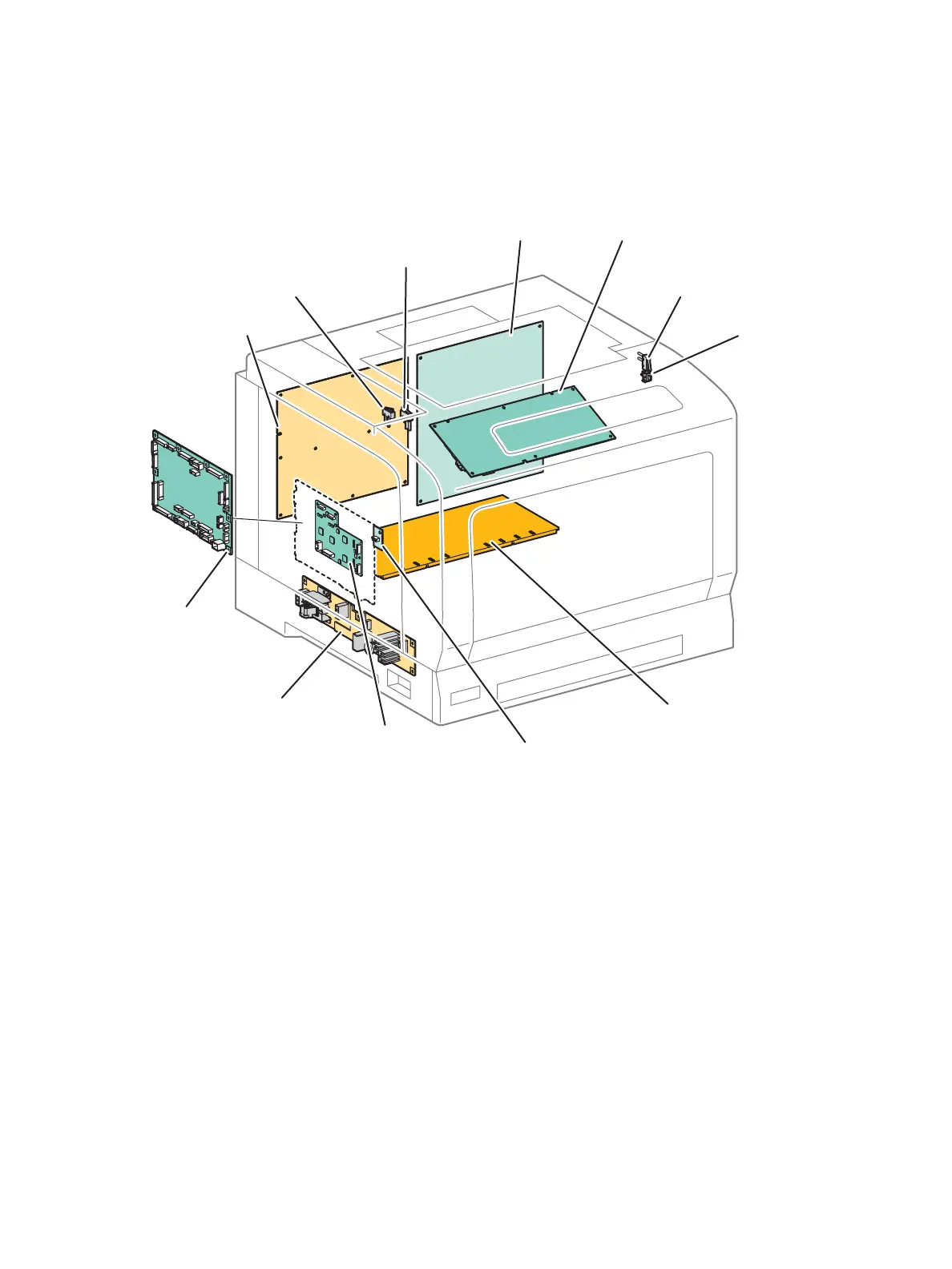
Electrical
The electrical system consists of the Image Processor (I/P) PWB, MCU PWB, AC PWB, LVPS PWB, HVPS1
PWB, HVPS2 PWB, and EEPROM PWB.
• Image Processor (I/P) PWB - This is the printer Controller. The I/P PWB receives print job data and
converts it to a rasterized format.
• MCU PWB - Communicates with the printer Controller and controls the components used in print
operation.
• AC PWB Assembly - Supplies the AC power to the LVPS PWB. It also turns the Lamp that heats the
Heat Roller in the Fuser Unit On and Off.
• LVPS PWB - Generates +24VDC, +5VDC, and +3.3VDC voltages from the AC power source to
supply the components that need them.
• HVPS1 PWB - Supplies the high voltage to the BCR that are part of the Imaging Unit of each color
and the Magnet Roller that are part of the Developer Housing Assembly of each color.
• HVPS2 PWB - Supplies the high voltage to the 1st BTR of each color and the Backup Roller that
are part of the IBT Belt Assembly.
• EEPROM PWB - This is a non-volatile memory that stores the printer data.
• Developer PWB - Supplies power to the Developer Motor.
• Front Cover Switch (Interlock Cap Switch) - Monitors the Open/ Close state of the Front Cover.
s7100-175
HVPS2 PWB
MCU PWB
AC PWB
LVPS PWB
HVPS1 PWB
IP PWB
Front Cover Switch
Front Cover Interlock Switch
Waste Cartridge Set Switch
Toner Cover Interlock Switch
EEPROM PWB
Developer PWB
(behind MCU PWB)

 Loading...


