Service Parts Disassembly
Xerox Internal Use Only Phaser 7100 Service Manual 4-97
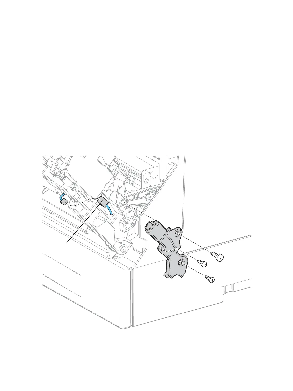
REP 4.6 Bypass Tray Feed Frame Assembly
PL 4.2.10
1. Remove Tray 1.
2. Remove the Control Panel Assembly (REP 1.12 Control Panel Assembly on page 4-29).
3. Remove the Bypass Tray Assembly (REP 3.5 Bypass Tray Assembly on page 4-73).
4. Remove the Bypass Tray Cover (REP 3.3 Bypass Tray Cover Assembly/ Exit 1 Cover/ Exit 2 Cover).
5. Remove the Front Cover Assembly (REP 1.15 Front Cover Assembly on page 4-35).
Note: If you wish to perform the next steps with the Front Cover Assembly removed, insert the
removed Left/ Right Pin (PL 3.1.10/ PL 3.1.13) back to their original position and temporarily fix
them in place before starting the procedure.
6. Remove 2 screws (silver, tapped, 8 mm) and one screw (silver, tapped, 12 mm) that secure the AC
Harness Cover (PL 4.2.8) and remove the Cover.
7. Disconnect the wiring harness connector P/J4751 that is connected to the Bypass Tray No Paper
Sensor (PL 4.4.3) and remove the harness through the hole.

 Loading...


