Service Parts Disassembly
Phaser 7100 Service Manual Xerox Internal Use Only4-228
REP 12.17 Image Processor (I/P) PWB
PL 12.4.1
CAUTION: PWB’s can be damaged by an electrostatic discharge. Observe all ESD procedures to
avoid component damage.
Notes:
• When replacing the Image Processor PWB, remember to remove the NVRAM from the
old PWB and install it to the new PWB.
– Take note although the printer can still work by using the new NVRAM on the new
Image Processor PWB, it will not inherit the setting values from the old one.
• The Image Processor PWB is installed to the HDD Bracket. Be sure remove the HDD
Bracket and then switch the SODIMM RAM.
• After replacing the Image Processor PWB with a new one, an error code will be displayed.
To clear the error, perform DC132 Machine Serial Number Settings on page 2-47 in
Service Diagnostics and set the Serial Number.
1. Remove the I/P PWB Cover Assembly (REP 1.5 Image Processor (I/P) PWB Cover Assembly on
page 4-19).
2. Remove the Rear Cover (REP 1.6 Rear Cover on page 4-20).
3. Remove the Right Side Cover (REP 1.11 Right Side Cover on page 4-27).
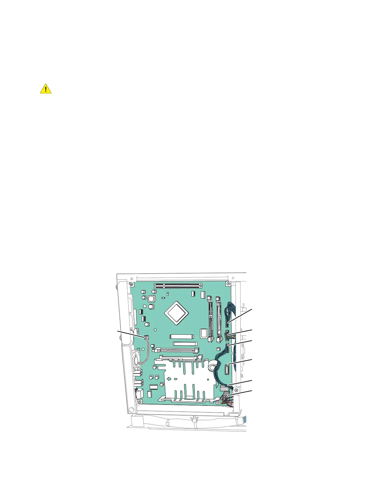
4. Disconnect the 5 wiring harness connectors (P/J300, P/J304, P/J305, P/J306, and P/J311) that are
connected to the Image Processor PWB.
Note: P/J302 and P/J310 need to be disconnected only when the HDD is installed.
s7100-348
P/J300
P/J302
P/J304
P/J305
P/J306
P/J310
P/J311

 Loading...


