Service Parts Disassembly
Phaser 7100 Service Manual Xerox Internal Use Only4-126
REP 6.3 Right Latch Assembly
PL 6.1.10
CAUTION: Do not expose the Imaging Unit to light for more than 5 minutes. Cover the Imaging
Unit to avoid damage. Do not touch the surface of the Imaging Unit.
1. Remove the Imaging Unit (Y/ M/ C/ K) (REP 6.0 Imaging Unit (Y/ M/ C/ K) on page 4-121).
2. Remove Tray 1.
3. Remove the I/P PWB Cover Assembly (REP 1.5 Image Processor (I/P) PWB Cover Assembly on
page 4-19).
4. Remove the Rear Cover (REP 1.6 Rear Cover on page 4-20).
5. Remove the Right Side Cover (REP 1.11 Right Side Cover on page 4-27).
6. Remove the Right Feeder Cover (REP 2.3 Right Feeder Cover on page 4-40).
7. Remove the Cam Cover (REP 9.7 Cam Cover on page 4-170).
8. Remove the IBT Retract Cam Assembly (REP 9.6 IBT Retract Cam Assembly on page 4-168).
9. Remove the Right Imaging Unit Guide Assembly (REP 6.1 Right Imaging Unit Guide Assembly on
page 4-123).
10. Remove the Left Imaging Unit Guide Assembly (REP 6.5 Left Imaging Unit Guide Assembly on
page 4-129).
11. Remove the Developer Housing Assemblies (Y/ M/ C/ K) (REP 8.1 Developer Housing Assembly (Y/
M/ C/ K) on page 4-137).
12. Remove the (K) Imaging Unit Guide Assembly (REP 6.4 (K) Imaging Unit Guide Assembly on
page 4-128).
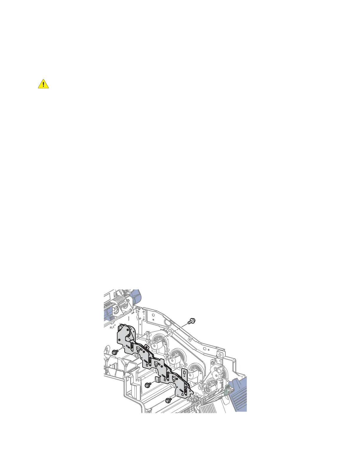
13. Remove 4 screws (silver, 6 mm) that secure the Right Latch Assembly to the printer and remove
the Right Latch Assembly.
Figure 1
s7100-131

 Loading...


