Service Parts Disassembly
Xerox Internal Use Only Phaser 7100 Service Manual 4-125
Removing the Imaging Unit CRUM Connector Assembly from the (K) Imaging Unit
Guide Assembly
CAUTION: Do not expose the Imaging Unit to light for more than 5 minutes. Cover the Imaging
Unit to avoid damage. Do not touch the surface of the Imaging Unit.
1. Remove the Imaging Unit (Y/ M/ C/ K) (REP 6.0 Imaging Unit (Y/ M/ C/ K) on page 4-121).
2. Remove Tray 1.
3. Remove the I/P PWB Cover Assembly (REP 1.5 Image Processor (I/P) PWB Cover Assembly on
page 4-19).
4. Remove the Rear Cover (REP 1.6 Rear Cover on page 4-20).
5. Remove the Right Side Cover (REP 1.11 Right Side Cover on page 4-27).
6. Remove the Right Feeder Cover (REP 2.3 Right Feeder Cover on page 4-40).
7. Remove the Right Imaging Unit Guide Assembly (REP 6.1 Right Imaging Unit Guide Assembly on
page 4-123).
8. Remove the Left Imaging Unit Guide Assembly (REP 6.5 Left Imaging Unit Guide Assembly on
page 4-129).
9. Remove the (K) Developer Housing Assembly (REP 8.1 Developer Housing Assembly (Y/ M/ C/ K)
on page 4-137).
10. Remove the (K) Imaging Unit Guide Assembly (REP 6.4 (K) Imaging Unit Guide Assembly on
page 4-128).
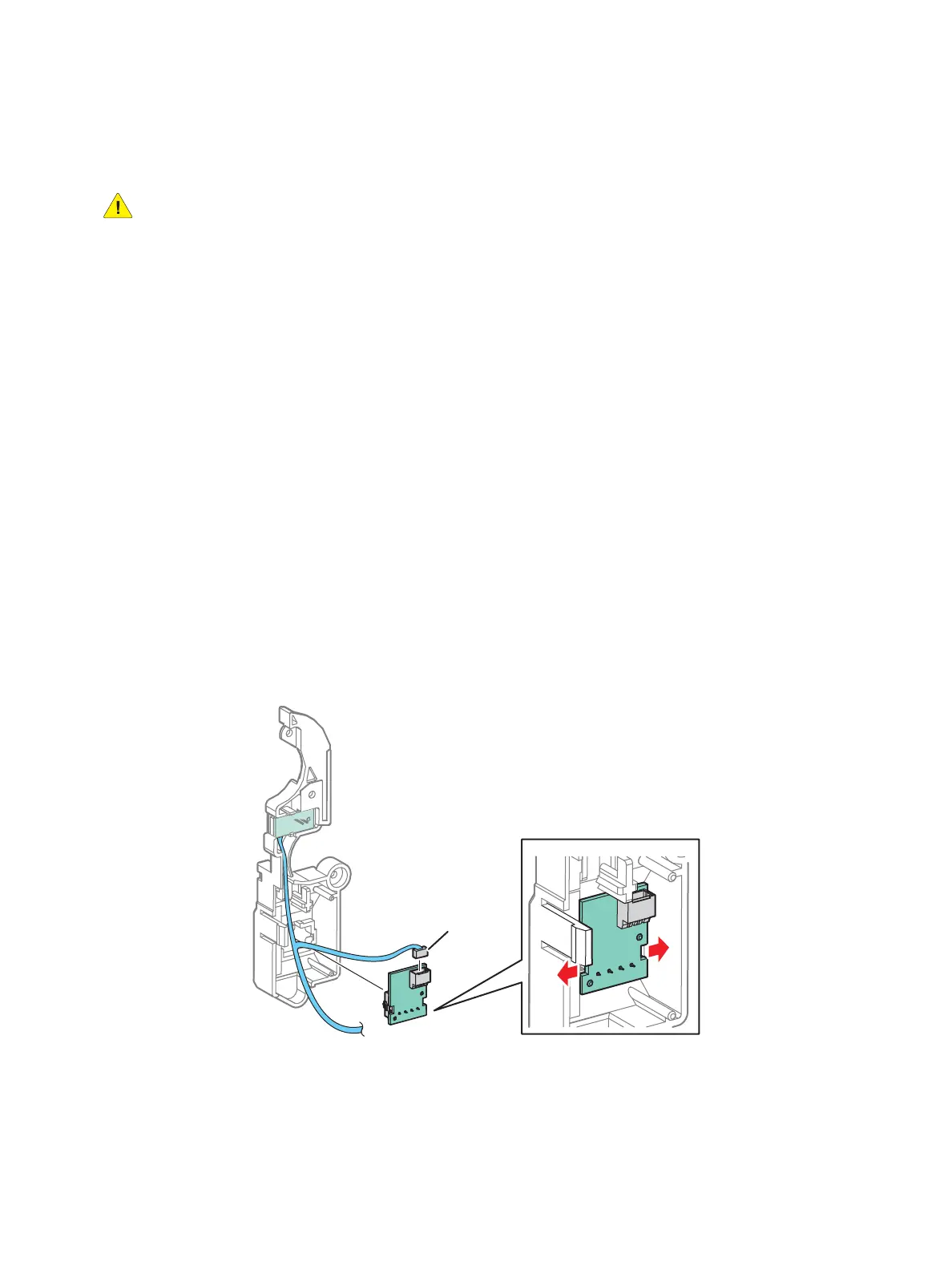
11. Disconnect the wiring harness connector from the Imaging Unit CRUM Connector.
12. Release the hooks that secure the Imaging Unit CRUM Connector.
13. Remove the Imaging Unit CRUM Connector Assembly.

 Loading...


