Error Troubleshooting
Xerox Internal Use Only Phaser 7100 Service Manual 2-23
Fault Diag
DC140 Analog Monitor
The DC140 Analog Monitor routine monitors each analog sensor for a certain period and displays the
respective value.
Component Input/ Run/ Stop
1. Enter Service Diagnostics menu (Entering Service Diagnostics on page 2-14).
2. Press Down Arrow and navigate to Diagnostics Fault Diag.
3. Press Right Arrow and navigate to Fault Diag. DC140 Monitor.
4. Press Right Arrow and navigate to DC140 Monitor Component Input.
5. Press Right Arrow to display the Component Input 000-000 screen.
Notes:
• Use Left/ Right Arrow to move the cursor and Up/ Down Arrow to change the number.
• When the cursor is at the left end of the Chain-Link Number, pressing Left Arrow returns
to the DC140 Monitor - Component Input screen at the previous level.
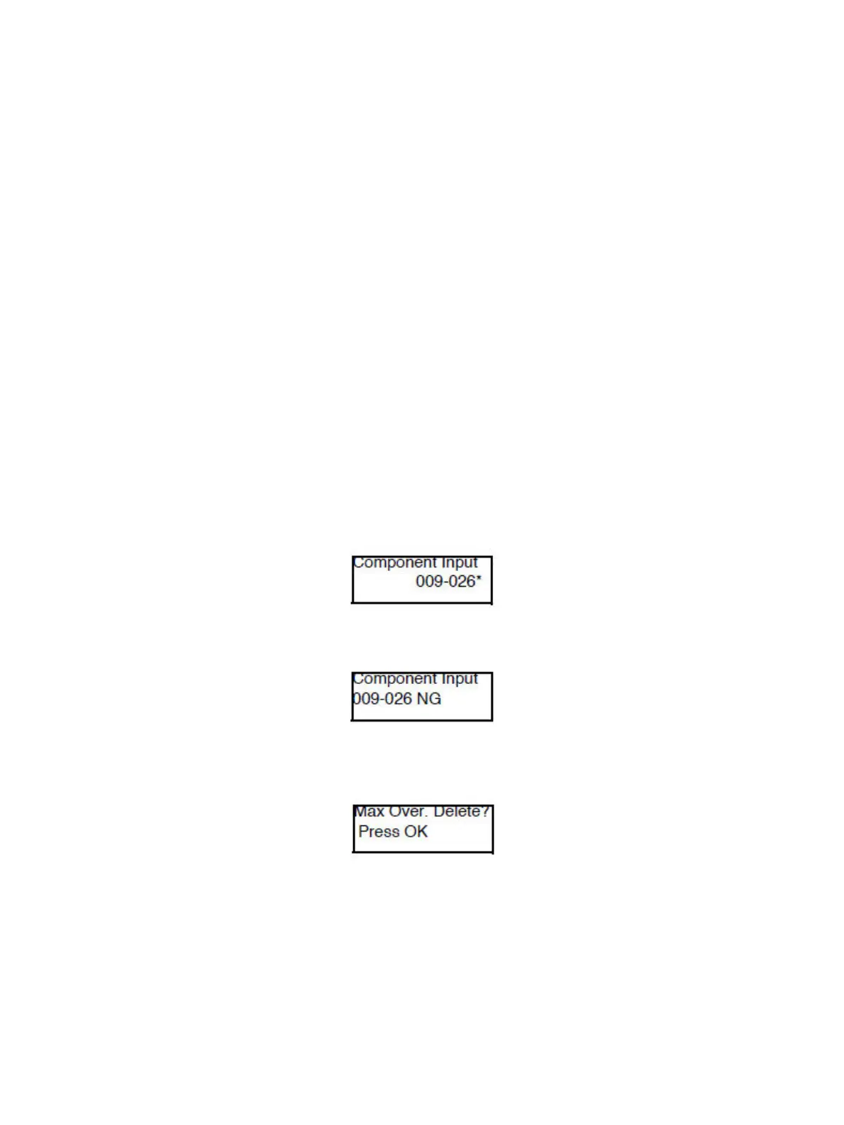
6. Press OK to confirm the Chain-Link Number. An “
*
” appears on the right side of the changed value.
After running a component in step 9 and then stopping the component, other components (up to
8 components) can be registered by repeating steps 5 and 6.
If the Chain-Link Number is not applicable, the NG screen appears.
When 8 of the components have been registered, the Max Over. Delete? - Press OK deletion
confirmation screen appears. Press OK to complete the registration.
 Loading...


