Service Parts Disassembly
Phaser 7100 Service Manual Xerox Internal Use Only4-124
REP 6.2 Imaging Unit CRUM Connector Assembly
PL 6.1.6
CAUTION: Do not expose the Imaging Unit to light for more than 5 minutes. Cover the Imaging
Unit to avoid damage. Do not touch the surface of the Imaging Unit.
Note: The Imaging Unit CRUM Connector can be removed from the Right Imaging Unit Guide
Assembly (PL 6.1.5) or the K Imaging Unit Guide Assembly (PL 6.1.11).
Removing the Imaging Unit CRUM Connector Assembly from the Right Imaging
Unit Guide Assembly
1. Remove the Imaging Unit (Y/ M/ C/ K) (REP 6.0 Imaging Unit (Y/ M/ C/ K) on page 4-121).
2. Remove Tray 1.
3. Remove the I/P PWB Cover Assembly (REP 1.5 Image Processor (I/P) PWB Cover Assembly on
page 4-19).
4. Remove the Rear Cover (REP 1.6 Rear Cover on page 4-20).
5. Remove the Right Side Cover (REP 1.11 Right Side Cover on page 4-27).
6. Remove the Right Feeder Cover (REP 2.3 Right Feeder Cover on page 4-40).
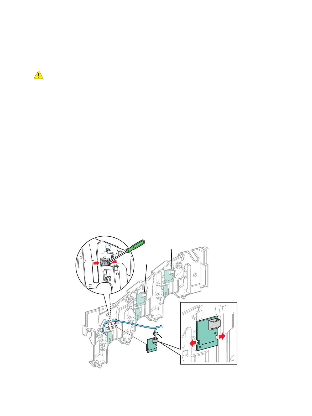
7. Disconnect the wiring harness connector from the Imaging Unit CRUM Connector.
8. Remove the Right Imaging Unit Guide Assembly (REP 6.1 Right Imaging Unit Guide Assembly on
page 4-123).
9. Release the hooks that secure the Imaging Unit CRUM Connector.
10. Remove the Imaging Unit CRUM Connector Assembly.
s7100-127
P/J4554
P/J4552
P/J4553

 Loading...


