Plug/Jack and Wiring Diagrams
Xerox Internal Use Only Phaser 7100 Service Manual 7-11
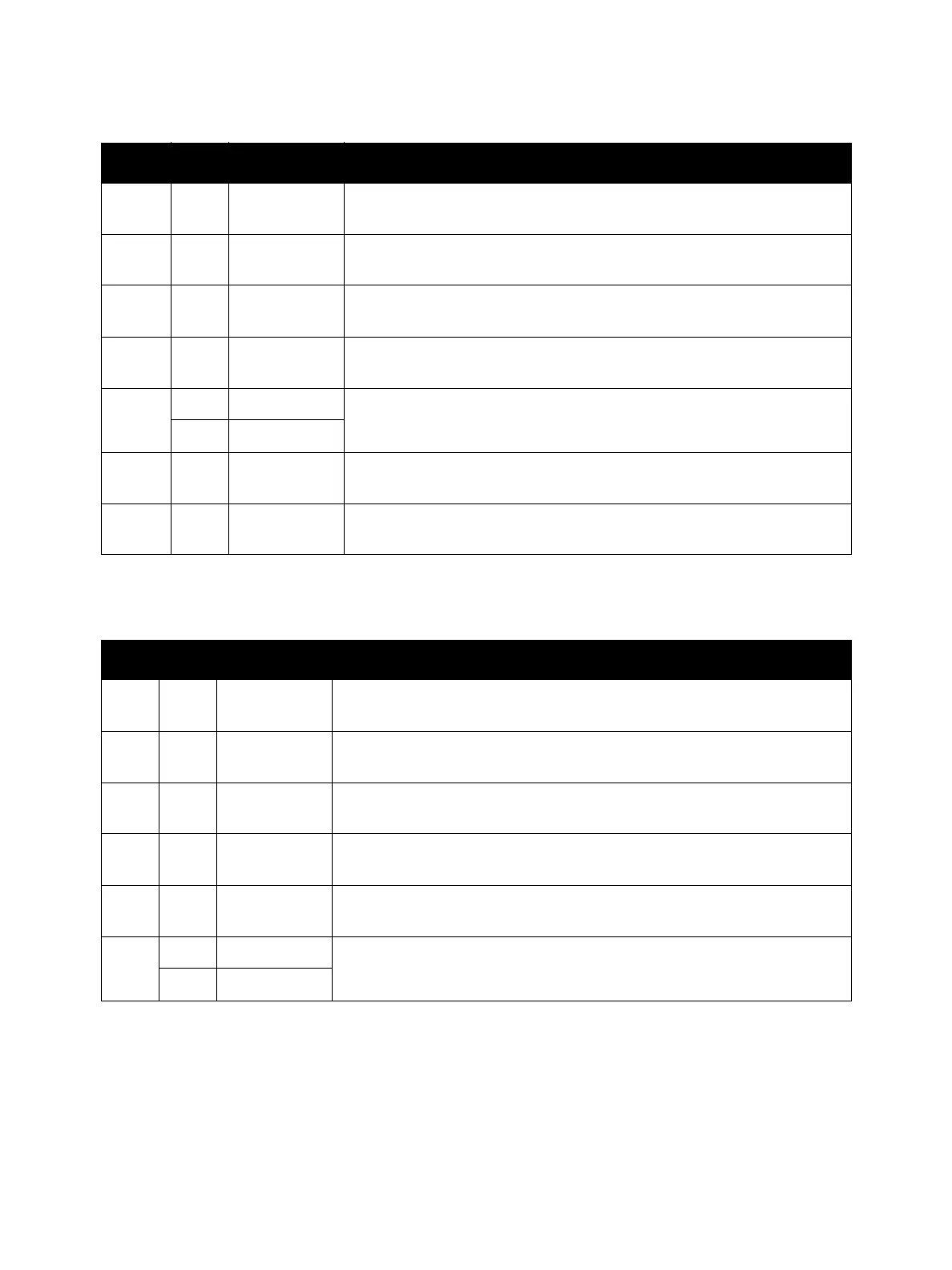
5245 6 I-108 Connection between the (Y/ M/ C) PR Harness Assembly (PL 11.1.22) and
the (Y/ M/ C) Drum Motor (YMC Drive Assembly) (PL 11.1.2).
5246 6 G-109 Connection between the (K) PR Harness Assembly (PL 11.1.23) and the
(K) Drum Motor (K Drive Assembly) (PL 11.1.12).
5247 8 E-106 Connection between the Main Harness Assembly (PL 12.3.1) and the
Paper Handling Motor Harness Assembly (PL 12.3.9).
5248 2 B-106 Connection between the Main Harness Assembly (PL 12.3.1) and the
Deve Motor Harness Assembly (PL 11.1.24).
5251 10 G-109 Connection between the Main Harness Assembly (PL 12.3.1) and the
Laser Unit (ROS Assembly) (PL 7.1.1).
11 E-111
5291 2 B-105 Connection between the LVPS PWB (PL 12.2.1) and the Toner Cover
Interlock Switch (PL 8.1.14).
5292 2 D-104 Connection between the Main Harness Assembly (PL 12.3.1) and the
Toner Cover Interlock Switch (PL 8.1.14).
Option Duplex Plug/Jack Designators
P/J Map Coordinates Remarks
125 12 F-107 Connection between the Duplex Jam Sensor (PL 14.3.17) and the Duplex
Sensor Harness Assembly (PL 14.3.9).
428 12 H-107 Connection between the Duplex PWB (PL 14.3.8) and the Duplex Relay
Harness Assembly (PL 14.3.19).
429 12 I-107 Connection between the Duplex PWB (PL 14.3.8) and the Duplex Motor (PL
14.2.1).
430 12 H-108 Connection between the Duplex PWB (PL 14.3.8) and the Duplex Sensor
Harness Assembly (PL 14.3.9).
431 12 H-107 Connection between the Duplex PWB (PL 14.3.8) and the Duplex In Clutch
Assembly (PL 14.2.20).
4672 12 A-104 Connection between the Duplex Harness Assembly (PL 4.2.18) and the
Duplex Relay Harness Assembly (PL 14.3.19).
13 F-102
Print Engine Plug/Jack Designators (Continued)
P/J Map Coordinates Remarks

 Loading...


