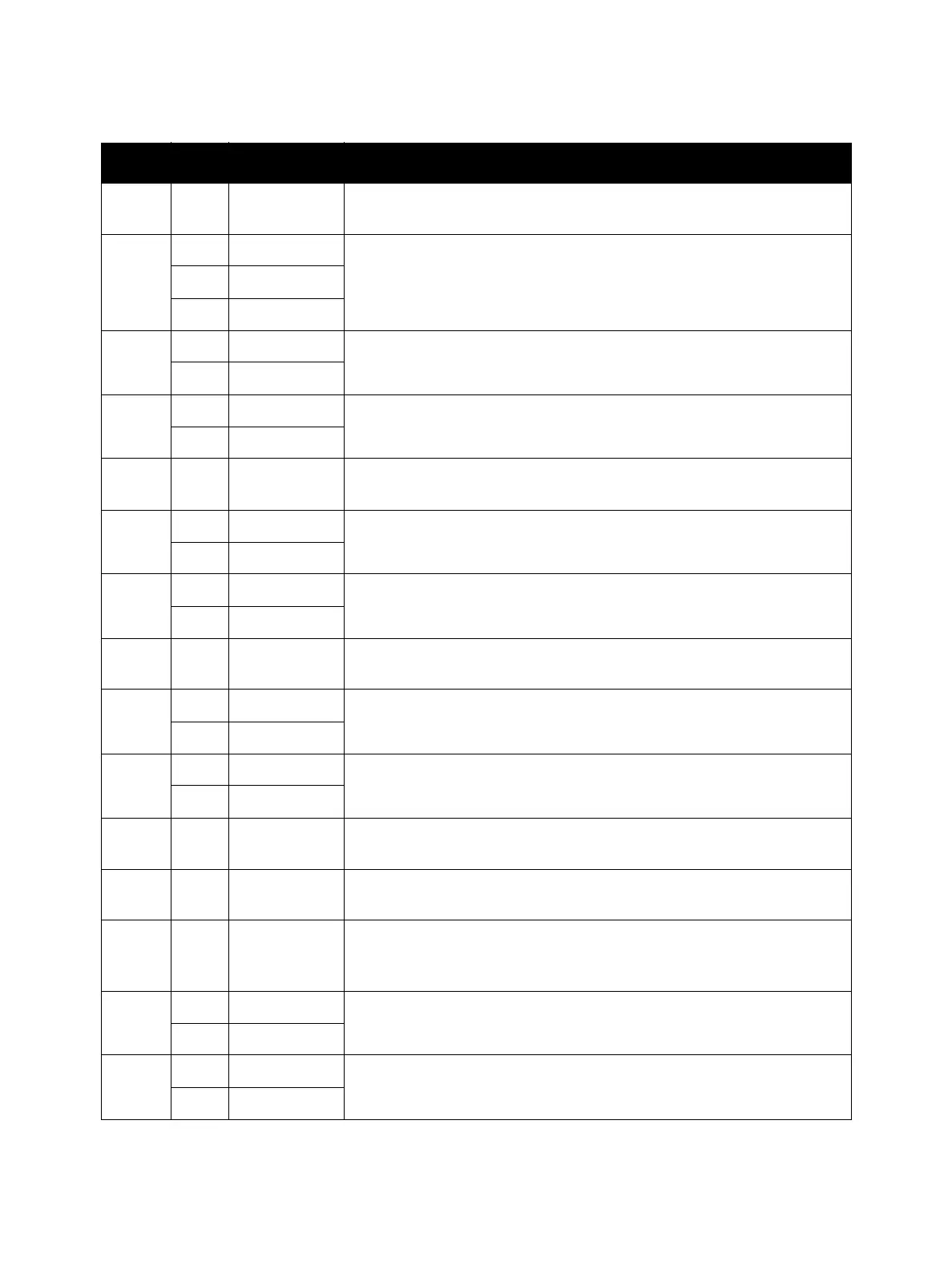
Plug/Jack and Wiring Diagrams
Phaser 7100 Service Manual Xerox Internal Use Only7-10
4741 2 C-106 Connection between the Developer Motor PWB (PL 11.1.16) and the
MCU PWB (PL 12.1.15).
4751 6 D-111 Connection between the Main Harness Assembly (PL 12.3.1) and the
Front Harness Assembly (PL 4.2.11).
9 B-111
13 C-111
4752 1 I-104 Connection between the Front Harness Assembly (PL 4.2.11) and the
Bypass Tray No Paper Sensor (PL 4.4.3).
13 A-104
4753 1 F-104 Connection between the Front Harness Assembly (PL 4.2.11) and the
Bypass Tray Feed Solenoid (PL 4.3.10).
13 G-108
4754 1 G-104 Connection between the Bypass Tray No Paper Sensor (PL 4.4.3) and
Interim Connector.
4755 1 D-104 Connection between the Front Harness Assembly (PL 4.2.11) and the
Fuser Unit Motor (Fuser Drive Assembly) (PL 4.2.16).
13 J-111
4761 6 G-110 Connection between the Main Harness Assembly (PL 12.3.1) and the (K)
CRUM X Harness Assembly (PL 6.1.15).
9 F-111
4762 2 I-106 Connection between the (K) CRUM Harness Assembly (PL 6.1.14) and the
(K) Imaging Unit CRUM Connector Assembly (PL 6.1.6).
5225 3 D-106 Connection between the Top Harness Assembly (PL 12.2.24) and the
Waste Cartridge Set Switch (PL 12.2.3).
5E-104
5226 3 H-105 Connection between the Top Harness Assembly (PL 12.2.24) and the
Front Cover Interlock Switch (PL 12.2.8).
5E-110
5231 10 I-109 Connection between the Main Harness Assembly (PL 12.3.1) and the
LVPS Fan Assembly (PL 12.2.22).
5241 2 B-106 Connection between the Developer Motor PWB (PL 11.1.16) and the
Main Harness Assembly (PL 12.3.1).
5242 8 G-106 Connection between the Paper Handling Motor Harness Assembly (PL
12.3.9) and the Paper Handling Motor (Paper Handling Drive Assembly)
(PL 11.1.19).
5243 6 H-109 Connection between the Main Harness Assembly (PL 12.3.1) and the (Y/
M/ C) CRUM X Harness Assembly (PL 6.1.15).
9 G-111
5244 6 J-109 Connection between the Main Harness Assembly (PL 12.3.1) and the (Y/
M/ C) Harness Assembly (PL 11.1.22).
9 I-111
Print Engine Plug/Jack Designators (Continued)
P/J Map Coordinates Remarks

 Loading...


