Plug/Jack and Wiring Diagrams
Xerox Internal Use Only Phaser 7100 Service Manual 7-29
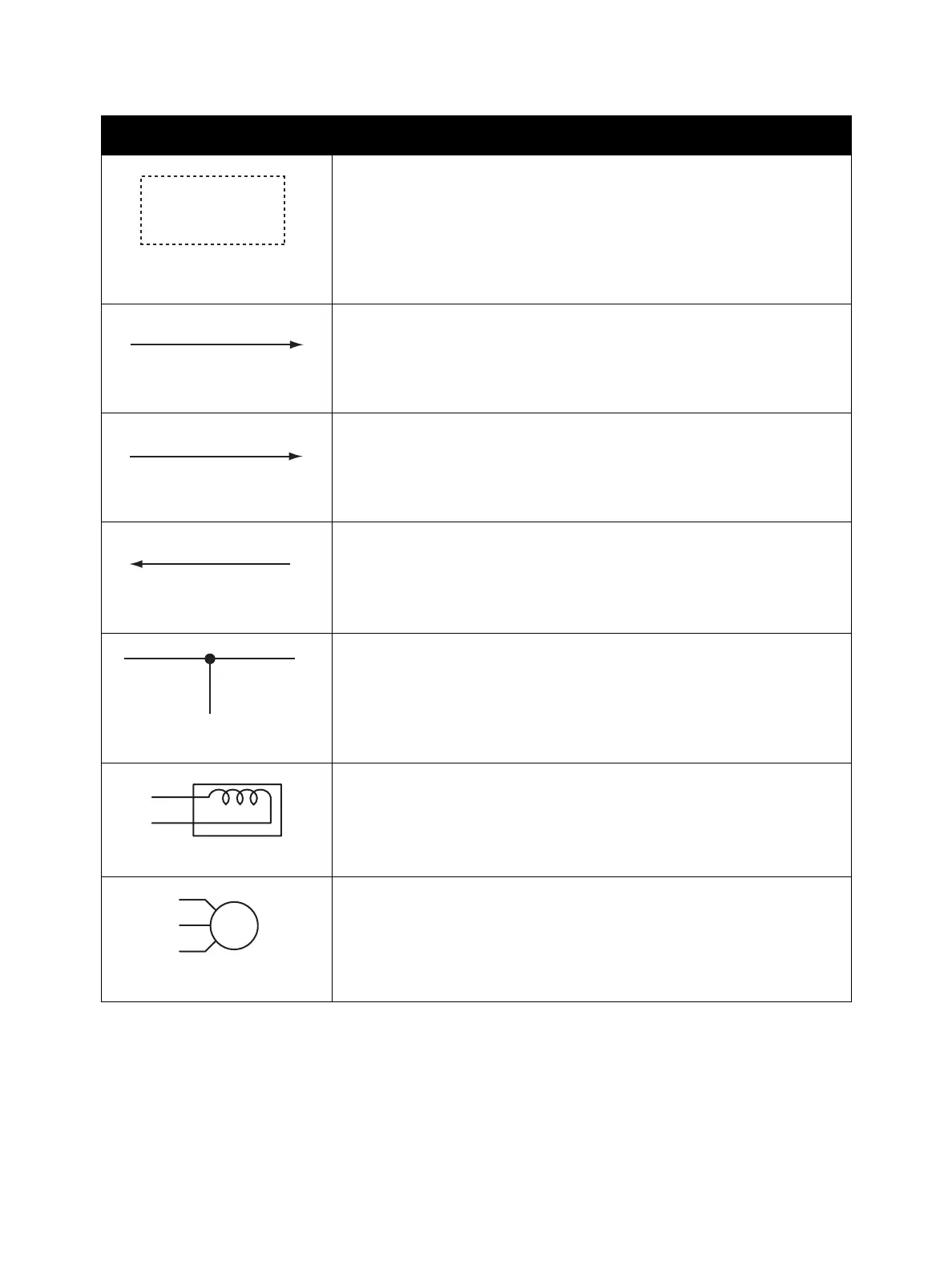
Denotes the control and its outline in the Board.
Denotes a connection between parts with harness or wires, attached with
signal name/contents.
Denotes the function, and logic value of the signal to operate the function
(Low: L, High: H).
The given voltage is for signal in high status.
The arrow indicates the direction of signal.
Denotes the function, and logic value of the signal when the function is
operated (Low: L, High: H).
The given voltage is for signal in high status.
The arrow indicates the direction of signal.
Denotes a connection between wires.
Denotes a Clutch or Solenoid.
Denotes a Motor.
Symbol Description
CLUTCH ON(L)+24V
Function Logic 1
EXIT SENSED(L)+3.3VDC
Function Logic 2

 Loading...


