AKD User Guide | 7 Configuring Drive Power
7.1 Power
7.1.1 Drive Setup for Power and Bus
The Power screen allows you to confirm Power Bus settings and accommodate external regeneration needs if
required. Nothing is required for this screen if you have no regeneration requirements. Review the data on the
screen to be certain the bus voltage is at the appropriate levels you expect (approximate input line AC voltage *
1.4). The other values are the appropriate limits for over voltage and under voltage for the particular drive. You
can select the undervoltage fault mode to trigger either only when the drive is enabled or always.
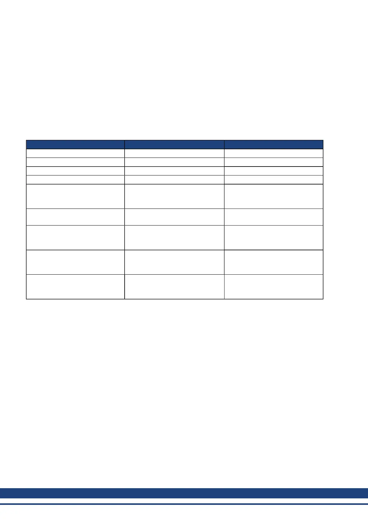
From the Power screen, you can view and configure the drive power settings as follows:
Button or Dialog Box Description Parameter
Measured Bus Voltage Reads the current DC bus voltage. VBUS.VALUE
Over Voltage Fault Level Reads the over voltage fault level. VBUS.OVFTHRESH
Under Voltage Fault Level Reads the under voltage fault level. VBUS.UVFTHRESH
Under Voltage Fault Mode Sets under voltage mode. VBUS.UVMODE
Regen Resistor Type
Sets the regen resistor type to either
-1-External Regen or 0-Internal
Regen (if available).
REGEN.TYPE
Regen Power
Reads the regen power (only visible
for external regen).
REGEN.POWERREGEN.POWER
External Regen Resistance
Sets the external, user-defined regen
resistor resistance (only visible for
external regen).
REGEN.REXT
External Regen Heat Up Time
Sets the external regen resistor ther-
mal protection time constant (only
visible for external regen).
REGEN.TEXT
External Regen Power
Sets the regen resistor's power fault
level for an external regen resistor
(only visible for external regen).
REGEN.WATTEXT
See 7.2 Regeneration for more information about regen resistors and sizing regen resistors.
7.1.2 Direct DC Mains Operation
Direct DC input is available on all standard AKD models. The DC input should be run into the AC input con-
nection. Positive and negative DC lines should use L1 and L2 connections (polarity is not critical). L1 and L2 con-
nections are found on either the X3 connector or the X4 connector depending on the model.
(see "Mains Supply Connection (X3, X4)" (=> p. 237) for more information on this connection).
The nominal level of DC voltage applied must be compatible with the voltage fault levels in the drive. You must
also consider voltage variations in the DC power supply above and below the nominal value so that nuisance
faults are avoided.
When you determine the maximum nominal DC voltage applied to the drive you should also consider the regen-
eration circuit, in addition to the over voltage level. Running the drive slightly below the over voltage level is not
possible because the drive does not have the capability to dissipate regenerated energy. This practice can also
be harmful to the regen circuit. A good practice is not to exceed the nominal DC voltage produced by a standard
AC installation. For the AKD-zzzzz06, 340 Vdc is the equivalent DC voltage for an 240 Vac supply and for the
AKD-xxxxx07, 680 Vdc is the equivalent DC voltage for a 480 Vac supply.
The voltage fault levels are also shown in the Power screen and depend on the voltage level of drive used.
Voltage ranges are as follows:
52 Kollmorgen | December 2010
 Loading...


