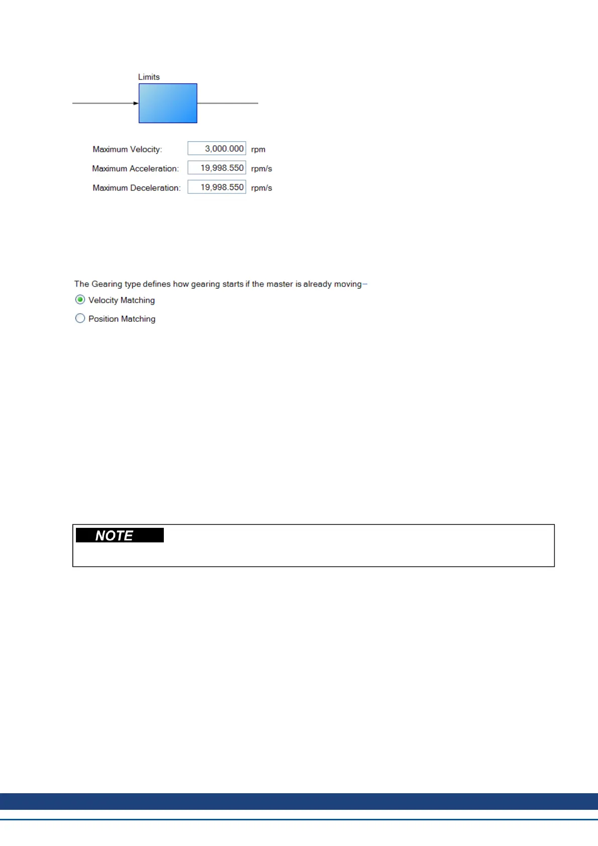
These limits (GEAR.ACCMAX, GEAR.DECMAX, GEAR.VELMAX) are applied only during gearing mode and
the units are consistent with speed and acceleration of the output motor. All other limits in the drive are active
along with gearing limits.
If the master is already moving when entering electronic gearing mode, velocity or position can be matched
(GEAR.MODE):
In Velocity Matching, the motor will ramp up to the same velocity with no concern over lost steps during the
acceleration period.
In Position Matching, the motor will match the position command from the switchover point by speeding up to
recover the lost steps during the acceleration period.
More information on each type of input mode is found here:
3 – AquadB (see Command encoder signal connection
4 – Pulse/Direction input (see Pulse / Direction signal connection)
5- Up/Down input (see Up / Down signal connection)
10.7.3 Determining Maximum Cable Length
When you use an external incremental encoder as an input to X9, you must determine the maximum allowable
cable length.
This information is only applicable when using an external encoder as either a sec-
ondary feedback input or a gearing command (DRV.EMUEMODE3). Not applicable
for any other X9 mode or when using two AKDs in a master/slave system.
The X9 port has a 5V output used to supply power to an external incremental encoder.
Themaximum cablelength depends on thecurrent draw of theexternal encoderand thecable typeconnecting the
X9port. The followingexample can be usedas a guide tocalculate themaximum cablelength foryour application.
X9 port characteristics:
Nominal Supply Voltage:5 V
Tolerance: 5%
Minimum Supply Voltage: 4.75 V
Maximum current: 0.25 A
Permitted wire gauge: 20-28 AWB (Typical for D9 connector)
Sample Application Hardware:
Example external encoder: Hengstler RI-36H (RS-422 encoder) used with X9 port.
Encoder Nominal Supply Voltage: 5V (+/- 10%)
AKD User Guide | 10 Configuring General Drive Settings
Kollmorgen | December 2010 99
 Loading...


