VL.ARPQ1 TO VL.ARPQ4
General Information
Type R/W Parameter
Description
Sets the Q of the pole (denominator) of anti-resonance (AR) filter 1; active
in opmodes 1 (velocity) and 2 (position) only.
Units None
Range 0.2 to 20
Default Value 0.5
Data Type Float
See Also
VL.ARPF1 TO VL.ARPF4, VL.ARZF1 TO VL.ARZF4, VL.ARZQ1 TO
VL.ARZQ4
Start Version M_01-02-00-000
Fieldbus Index/Subindex Object Start Version
EtherCAT COE
and CANopen
3406h/5 VL.ARPQ1
3406h/6 VL.ARPQ2
3406h/7 VL.ARPQ3
3406h/8 VL.ARPQ4
M_01-02-00-000
Modbus
816 VL.ARPQ1
818 VL.ARPQ2
820 VL.ARPQ3
822 VL.ARPQ4
M_01-03-00-000
Description
VL.ARPQ1 sets the Q (quality factor) of the pole (denominator) of AR filter 1. This value is Q
P
in the approximate
transfer function of the filter:
ARx(s) = [s²/(2πF
Z
)²+s/(Q
Z
2πF
Z
) + 1]/ [s²/(2πF
P
)² +s/(Q
P
2πF
P
) + 1]
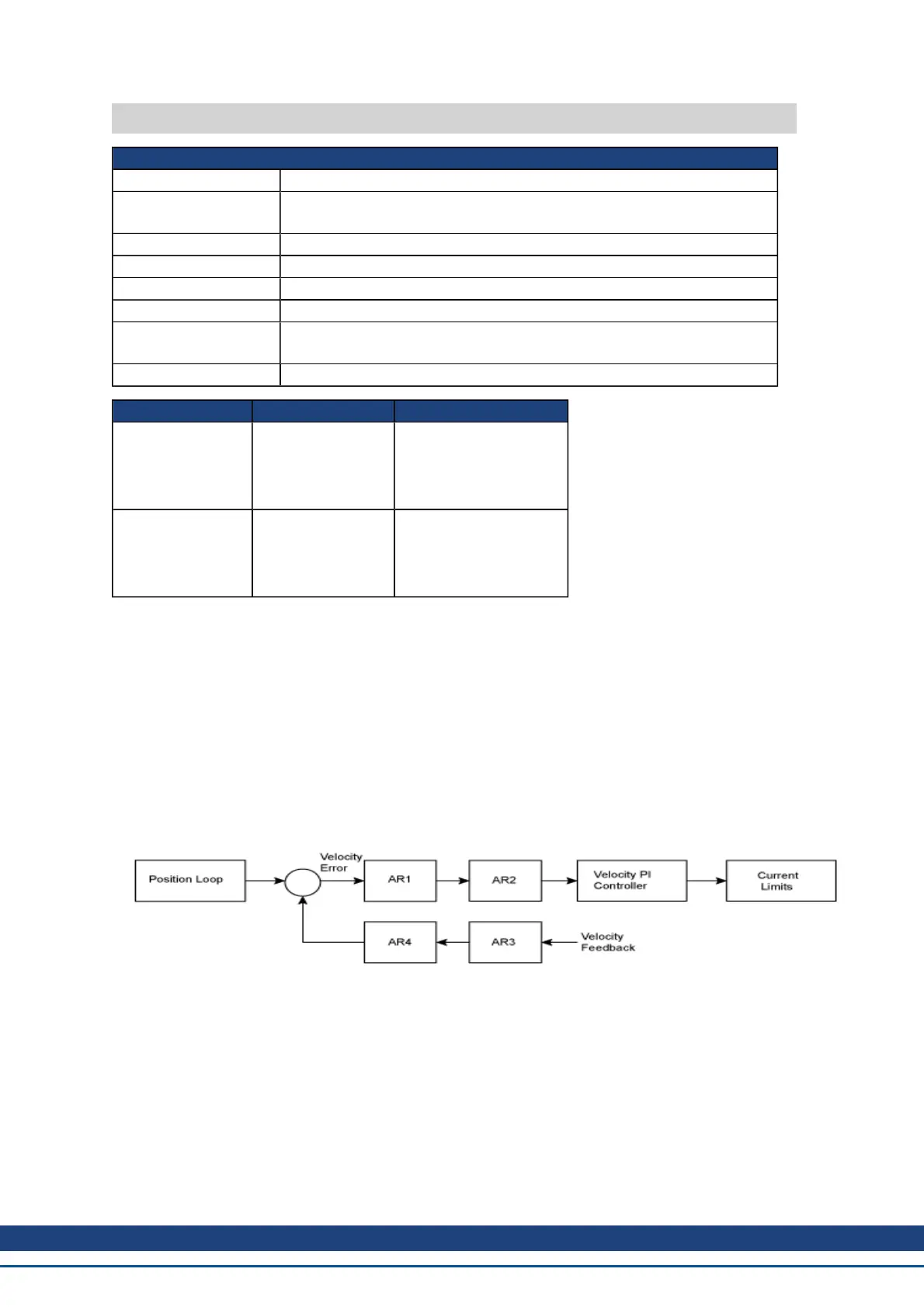
The following block diagram describes the AR filter function; note that AR1 and AR2 are in the forward path,
while AR3 and AR4 are applied to feedback:
AR1, AR2, AR3, and AR4 are used in velocity and position mode, but are disabled in torque mode.
Discrete time transfer function (applies to all AR filters)
The velocity loop compensation is actually implemented as a digital discrete time system function on the DSP.
The continuous time transfer function is converted to the discrete time domain by a backward Euler mapping:
s ≈ (1-z
-1
)/t, where t = 62.5 µs
The poles are prewarped to F
P
and the zeros are prewarped to F
Z
.
Related Topics
AKD User Guide | VL Parameters
Kollmorgen | December 2010 623
 Loading...


