AKD User Guide |
20.5.2 Construction of the Communication Object Identifier
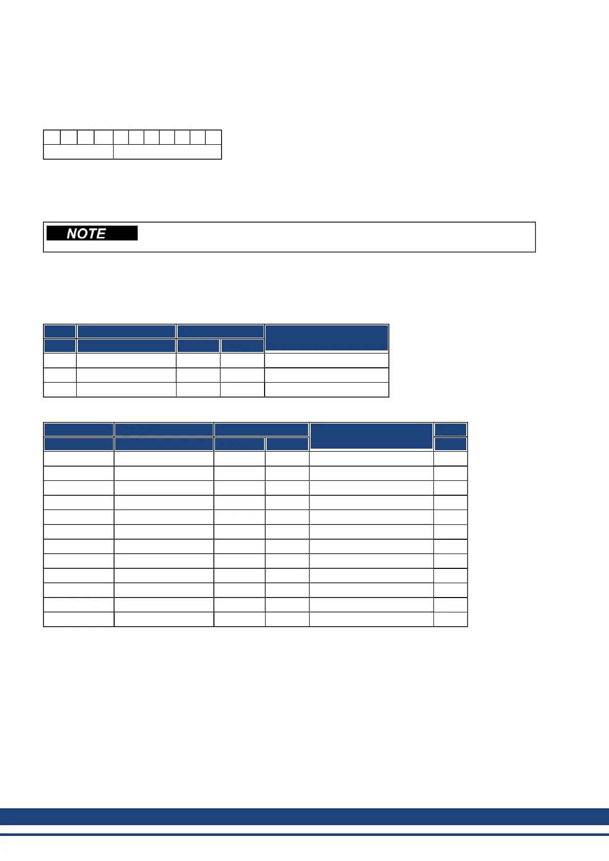
The following diagram shows the layout of the COB Identifier (COB-ID). The Function Code defines the inter-
pretation and priority of the particular object.
10 9 8 7 6 5 4 3 2 1 0
Function-Code Module-ID
Bit 0 .. 6
Module ID (drive's CAN-bus address, range 1 to 127; is set up in WorkBench or the drive,)
Bit 7 to 10
Function Code (number of the communication object that is defined in the server)
If an invalid station number (=0 or >127) is set, then the module will be set inter-
nally to 1.
The following tables show the default values for the COB Identifier after switching on the drive. The objects,
which are provided with an index (Communication Parameters at Index), can have a new ID assigned after the
initialization phase. The indices in brackets are optional.
Predefined broadcast objects (send to all nodes):
Object Function code (binary) Resulting COB-IDs Communication parameters
at index
Dec. Hex.
NMT 0000 0 0 —
SYNC 0001 128 80 (1005)
TIME 0010 256 100 not supported
Predefined Peer-to-Peer objects (node sends to node):
Object Function code (binary) Resulting COB-IDs Communication parameters
at index
Priority
Dec. Hex.
EMERGENCY 0001 129..255 81..FF — high
TPDO 1 0011 385..511 181..1FF 1800
RPDO 1 0100 513..639 201..27F 1400
TPDO 2 0101 641..767 281..2FF 1801
RPDO 2 0110 769..895 301..37F 1401
TPDO 3 0110 897..1023 381..3FF 1802
RPDO 3 1000 1025..1151 401..47F 1402
TPDO 4 1001 1153..1279 481..4FF 1803
RPDO 4 1010 1281..1407 501..57F 1403
SDO (tx*) 1011 1409..1535 581..5FF
SDO (rx*) 1100 1537..1663 601..67F
Nodeguard 1110 1793..1919 701..77F (100E) low
*tx = direction of transmission: AKD => Master
rx = direction of transmission: Master => AKD
41 Kollmorgen | December 2010

 Loading...


