19.14 I/O Connection
All standard digital and analog I/O signals are connected to X7 and X8.
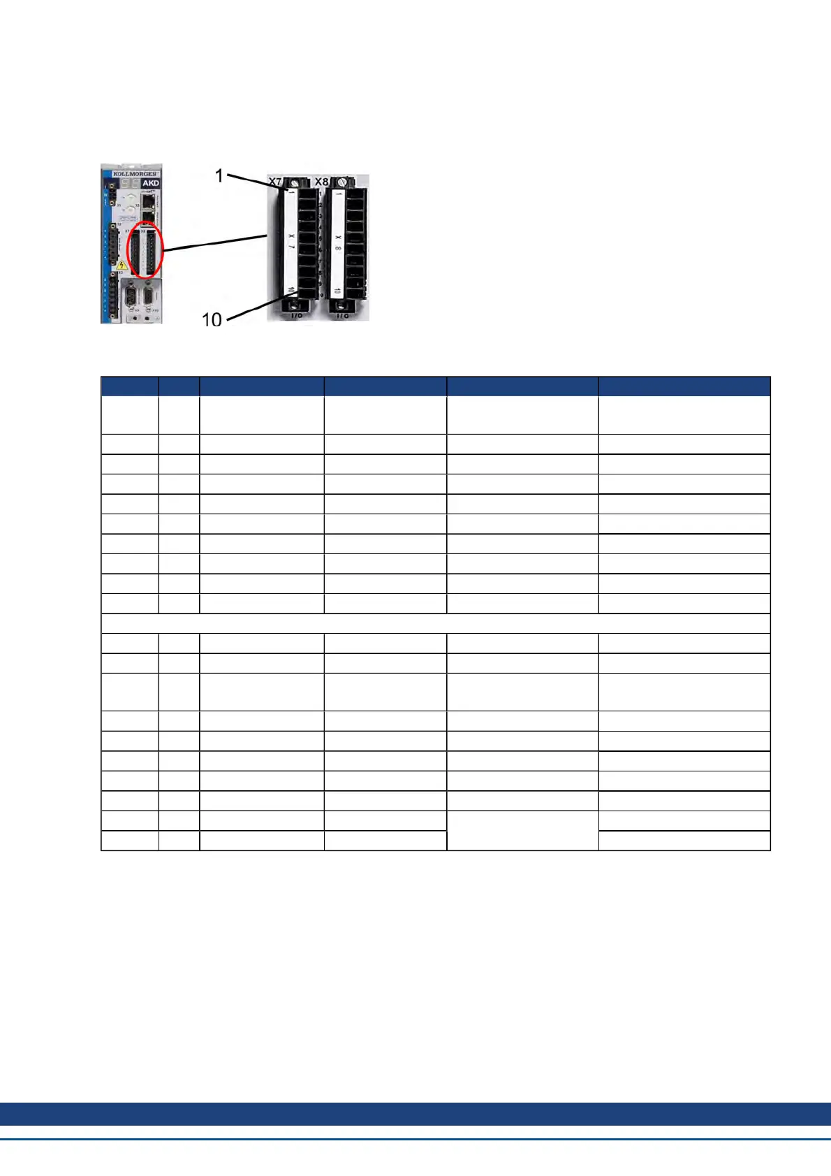
19.14.1 I/O Connectors (X7 and X8)
Conn. Pin Signal Abbreviation Recommended Function Specials
X7 1 Digital Common X7 DCOM7
Common line for
X7 pins 2, 3, 4, 9, 10
N/A
X7 2 Digital Input 7 DIGITAL-IN 7 Programmable N/A
X7 3 Digital Input 4 DIGITAL-IN 4 Programmable N/A
X7 4 Digital Input 3 DIGITAL-IN 3 Programmable N/A
X7 5 Digital Output 2- DIGITAL-OUT2- Programmable N/A
X7 6 Digital Output 2+ DIGITAL-OUT2+ Programmable N/A
X7 7 Digital Output 1- DIGITAL-OUT1- Programmable N/A
X7 8 Digital Output 1+ DIGITAL-OUT1+ Programmable N/A
X7 9 Digital Input 2 DIGITAL-IN 2 Reference point high speed
X7 10 Digital Input 1 DIGITAL-IN 1 Home switch high speed
X8 1 Fault Relay Output Fault Relay Output N/A N/A
X8 2 Fault Relay Output Fault Relay Output N/A N/A
X8 3 Digital Common X8 DCOM8
Common line for
X8 pins 4, 5, 6
N/A
X8 4 Digital Input 8 DIGITAL-IN 8 Output stage enable not programmable
X8 5 Digital Input 6 DIGITAL-IN 6 Negative limit switch N/A
X8 6 Digital Input 5 DIGITAL-IN 5 Positive limit switch N/A
X8 7 Analog Ground AGND Analog GND N/A
X8 8 Analog Output + Analog-Out Actual velocity voltage N/A
X8 9 Analog Input - Analog-In-
Velocity set point
N/A
X8 10 Analog Input + Analog-In+ N/A
DigitalcommonlinesforX7andX8arenotcommontoeachother.
TheDCOMxlineshouldbeconnectedtothe0VoftheI/Osupplywhenusingsensorsoftype"Source"withdigital
inputs.
TheDCOMxlineshouldbeconnectedtothe24VoftheI/Osupplywhenusingsensorsoftype"Sink" withdigitalinputs.
AKD User Guide | Connection Diagrams
Kollmorgen | December 2010 239
 Loading...


