8.11.2.1 Setting the Capture Source (CAP0.TRIGGER)
The capture source determines which input on the drive causes the position capture to trigger.
Capture Source Options:
0 – DIN 1through 6 – DIN 7. These options trigger on the Digital Input 1 pin through Digital Input 7
pin, respectively.
7 – RS485 Input 1 through 9 – RS485 Input 3. These options trigger on the RS485 Input 1 pin
through RS485 Input 3 pin, respectively.
10 – Primary Index. This option triggers on the primary encoder index.
8.11.2.2 Setting the Capture Mode (CAP0.MODE)
The capture mode determines what information is saved on the drive when the capture triggers.
Capture mode options:
0 – Standard Position. Captures the motor position in drive units
1 – Drive Internal Time. Captures the time of the trigger in ns
2 – Distributed Clock Time. Captures the network (Ethercat) distributed clock time
3 – Primary Encoder Signal. Captures the motor postion triggering on primary encoder index.
This mode automatically rearms after each trigger.
If either 0 - Standard Position or 3 - Primary Encoder Signal is selected, delays may occur and are asso-
ciated with feedback devices that are digital or interpolated .
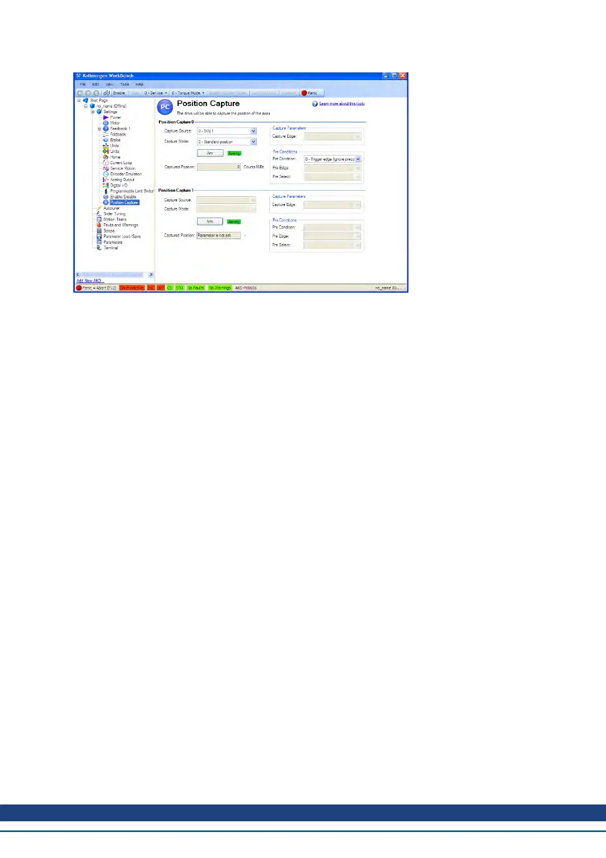
8.11.2.3 Arming and Retrieving the Capture Value (CAP0.EN and CAP0.T)
CAP0.EN arms the capture and CAP0.T retrieves the capture value. Once you have configured the capture, you
must arm it before it will trigger. Click Arm (1) to arm the capture.
Once the capture is armed, when it triggers, the captured value will be displayed below the Arm button (2).
8.11.2.4 Setting the Capture Edge (CAP0.EDGE)
The capture edge determines which input state change triggers the capture.
Capture Edge Options:
1 – Rising Edge. Captures when the input signal goes high, from a low state.
2 – Falling Edge. Captures when the input signal goes low, from a high state.
3 – Both Edges. Captures any time the input signal changes state.
AKD User Guide | 8 Configuring Motor Settings
Kollmorgen | December 2010 77

 Loading...


