AKD User Guide | 11 Using Command Source and Operating Modes
Manual adjustments to the current loop proportional gain parameter are not nor-
mally required during the motor tuning procedure. If manual adjustments are
made to the current loop proportional gain parameter, repeating the motor setup
procedure will overwrite the changes and restore the value to the Kollmorgen cal-
culated value.
Related Parameters
IL Parameters
DRV.OPMODE
11.4 Velocity Loop
11.4.1 Overview
The velocity loop is active when the drive operates in velocity mode (DRV.OPMODE = 1) or position mode
(DRV.OPMODE = 2). The parameters that govern the velocity loop are shown in the Velocity Loop view. The var-
ious types of tuning for the AKD adjust these parameters automatically, so you normally do not need to adjust the
velocity loop parameters in the velocity loop screen.
A detailed block diagram for the velocity loop is included in Block Diagrams.
11.4.2 Tabs in the Velocity Loop View
The velocity view includes an active block diagram. If you click on a block in the diagram, the appropriate tab
opens below.
l Ramp limiter . The ramp limiter consists of the acceleration limits of the AKD. These acceleration limits
override both motion task and electronic gearing acceleration limits, so they must be set higher than the
highest required motion task acceleration or gearing acceleration value. These acceleration and decel-
eration limits are also shown in the Service Motion view and the Limits view (DRV.ACC and DRV.DEC).
l Velocity clamp. The velocity clamp affects the maximum speed of the drive when the command source
is service (DRV.CMDSOURCE = 0). This speed limit affects motion commanded in service motion and
in motion tasks. These limits are also found in the limit screen on WorkBench. (VL.LIMITP and VL.LI-
MITN)
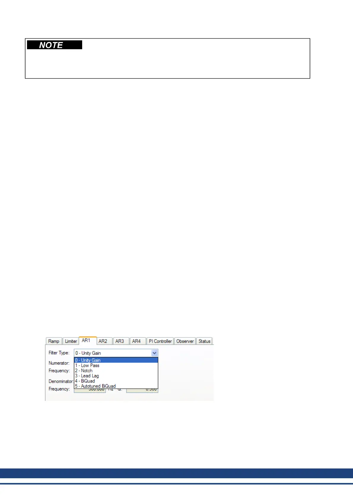
l AR1, AR2, AR3, AR4: These values are the independent bilinear quadratic (bi-quad) filters inside the
drive. AR1 and AR2 are in the forward path and AR3 and AR4 are in the feedback path. These bi-quad
filters can each be configured in five different modes.
0–Unity Gain. The filter is off, and it will not affect the loop.
1–Low Pass. In modes 1, 2, and 3, the bi-quad filter is configured for each respective type of fil-
tering. The Edit Parameters field is used to set up the filter. The actual bi-quad filter values are
shown to the left:
114 Kollmorgen | December 2010
 Loading...


