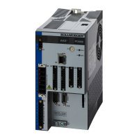
The drive offers the flexibility to use connector X9 for an encoder emulation output. This output can be set up
using the Encoder Emulation view (see 8.4.1 Encoder Emulation .
The Emulation Modebox offers three settings for Encoder Emulation mode:
Mode 0 – The connector is free to use as an input
Mode 1 – The X9 connector is now set up as an encoder emulation with a once per rev index pulse
(resolution is set in the next parameter (Emulation Resolution).
Mode 2 – The X9 connector is now set up as an absolute index pulse
Emulation Resolution sets the resolution desired for the output of the emulated encoder.
The Index or Absolute offset is dependent on which emulation mode is selected, allowing you to set an offset
for either the index pulse or absolute pulse.
A check box allows you to consider the motor direction based on the encoder output.
8.4.1 Encoder Emulation
8.4.1.1 Overview
The encoder emulation (EEO) connector (X9) can be used as an either an output or an input. As an output, you
can use this connector for position feedback to an analog controller and for configuring the drive as the master in
a master/slave system.You can also use X9 connector as an input for controlling the drive through an A/B, pulse
and direction, or up/down command. Common applications for this input include using the drive with a stepper
controller and configuring the drive as the slave in a master/slave system.
8.4.1.2 Using Encoder Emulation
You can configure the X9 connector from the Encoder Emulation screen by setting the connector function, res-
olution, and (where applicable) input position. The Electronic Gearing screen also has provisions for setting the
function of the X9 connector.
8.4.1.3 Function Settings
Function settings for the X9 connector are assigned through the "DRV.EMUEMODE" (=> p. 359) parameter.
Mode 0:Disable X9
Input (No EEO Output). The EEO connector (X9) is configured as an input. See Feedback 2 (FB2) for definitions
for the EEO Connector (X9). Note that this mode is also deprecated and will behave as it did with firmware ver-
sions prior to M_01-03-00-000.
In earlier firmware versions, this mode indicates that the EEO connector is not operative.
Output Modes 1 and 2
In the output modes, the drive calculates the motor shaft position from the cyclic- absolute signals of the primary
feedback, generating incremental-encoder compatible pulses from this information. Pulse outputs on the SubD
connector X9 are three signals: A, B and index, with 90° phase difference (i.e. in quadrature, hence the alter-
native term “A quad B” output), with a zero pulse.
If you are using the AKD as a master, the slave drives use the master's encoder output signals as command
input and follows these commands (velocity and direction).The drives operate from an internal supply voltage.
Mode 1– Aquad B with once per rev index pulse
Output Mode 1 - A quad B with Once per Rev Index Pulse Connection Diagram
AKD User Guide | 8 Configuring Motor Settings
Kollmorgen | December 2010 69

 Loading...