AKD User Guide | PLS Parameters and Commands
PLS.P1 TO PLS.P8
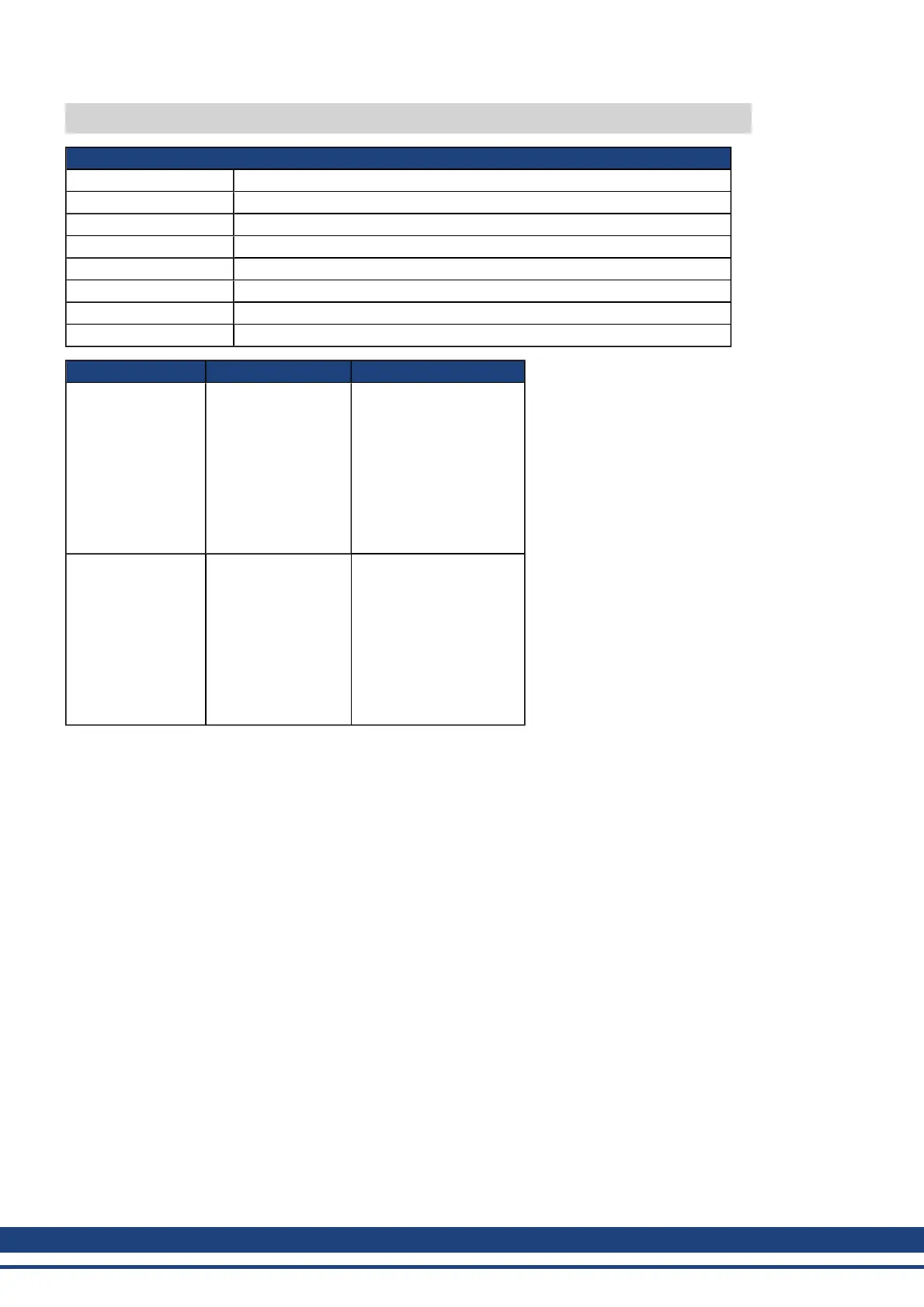
General Information
Type R/W Parameter
Description Sets the trigger point for programmable limit switches.
Units Depends on UNIT.PROTARY or UNIT.PLINEAR
Range N/A
Default Value 0
Data Type Float
See Also UNIT.PROTARY
Start Version M_01-02-03-000
Fieldbus Index/Subindex Object Start Version
EtherCAT COE
and CANopen
34A0h/1 PLS.P1
34A0h/2 PLS.P2
34A0h/3 PLS.P3
34A0h/4 PLS.P4
34A0h/5 PLS.P5
34A0h/6 PLS.P6
34A0h/7 PLS.P7
34A0h/8 PLS.P8
M_01-02-03-000
Modbus
622 (64-Bit) PLS.P1
626 (64-Bit) PLS.P2
630 (64-Bit) PLS.P3
634 (64-Bit) PLS.P4
638 (64-Bit) PLS.P5
642 (64-Bit) PLS.P6
646 (64-Bit) PLS.P7
650 (64-Bit) PLS.P8
M_01-03-00-000
Description
PLS.P1 to PLS.P8 define the trigger point of the PLS. For further information about how these parameters affect
PLS behavior, see the PLS.UNITS parameter description.
Related Topics
10.8 Programmable Limit Switch
556 Kollmorgen | December 2010

 Loading...


