AKD User Guide | 8 Configuring Motor Settings
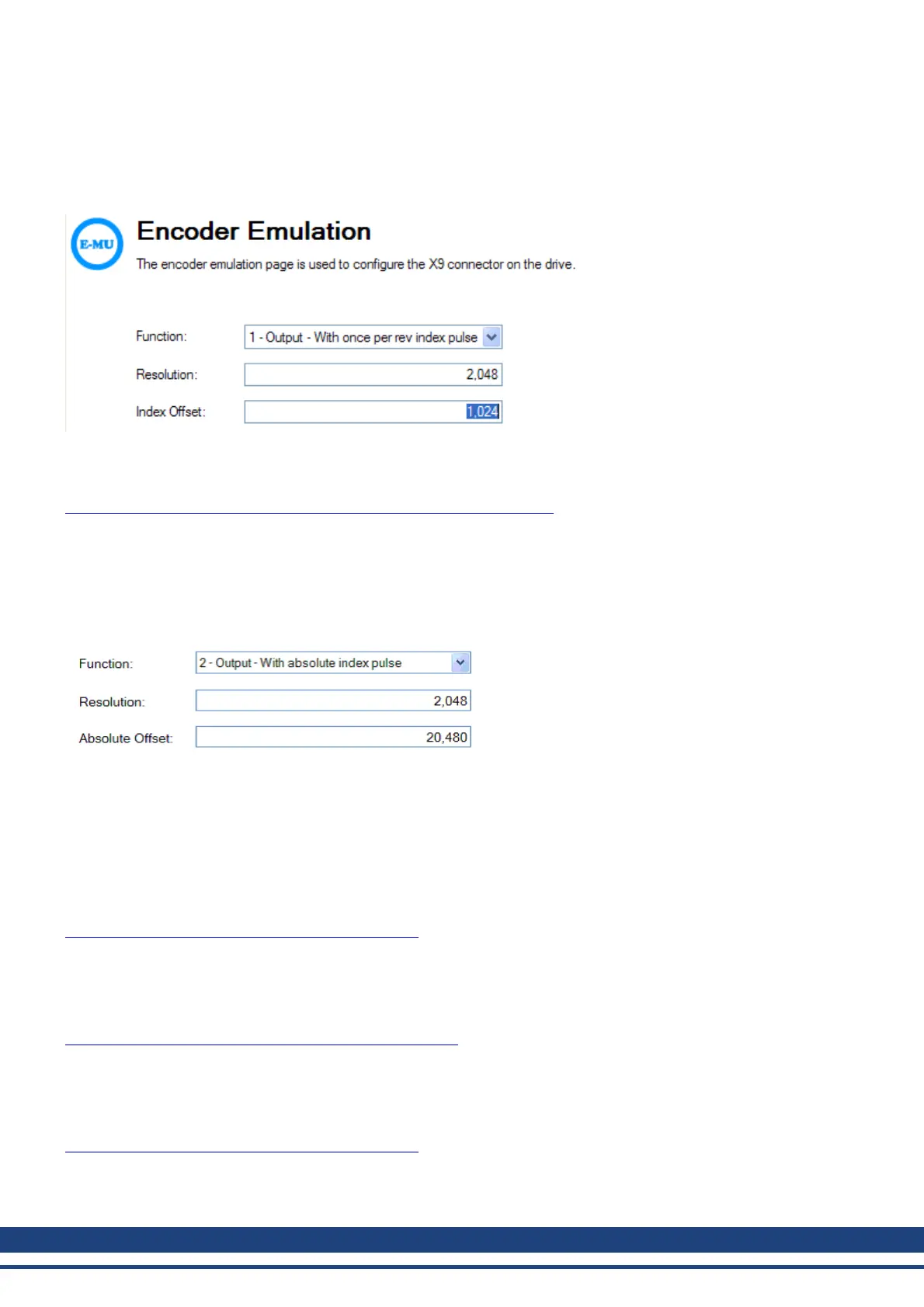
Thisoutput modesimulates anencodersignalfrom theX9porttoanotherAKD orexternal controller. EEOresolution
("DRV.EMUERES"(=> p.361))defineshow manycounts areoutputtedforonerevolutionof theprimary feedback.
Index offset ("DRV.EMUEZOFFSET" (=> p. 362)) determines the point during the revolution of the primary feed-
back when the index pulse (X9 pins 7&8) is output through the X9 port. The pulse will occur once every revolution
of the primary feedback at the positive value of the offset.
In this case, the Index is offset 180 degrees, or halfway through the revolution of the primary feedback.
Mode 2– A quad B with absolute index pulse
Output Mode 2 - A quad B with Absolute Index Pulse Connection Diagram
When mode 2 is chosen, a box will appear for an absolute index point to be entered ("DRV.EMUEMTURN" (=>
p. 360)). The absolute index pulse will be output when the X9 output position reaches the assigned value. The
index will be output when the feedback position in counts matches this parameter. In the example below, the
absolute index pulse output will occur after 10 positive revolutions of the motor. The absolute index is referenced
from the zero point of the primary feedback and is reset when the drive is homed.
Input Modes 3, 4, and 5
The X9 connector is also capable of input modes. These input modes correspond to the signal types described
below. The Electronic Gearing screen also includes provisions for setting the function of the X9 connector for
input modes.
Mode 3-A quad B signals
Input Mode 3 - A quad B Signals Connection Diagram
Input mode 3 allows an A quad B encoder or the encoder emulation output of another drive to be connected and
used as a commander encoder, dual loop feedback, gearing, or camming input.
Mode 4-Pulse/direction signals
Input Mode 4 - Pulse/direction Signals Connection Diagram
Input mode 4 allows the drive to be connected to a third-party stepper-motor controller. The number of steps can
be adjusted so that the drive can be adapted to match the step-direction signals of any stepper controller.
Mode 5-Up/down signals
Input Mode 5 - Up/down Signals Connection Diagram
The drive can be connected to a third-party controller which delivers up-down signals.
Mode 6-Output – with once per rev index and Input – Step and Direction
70 Kollmorgen | December 2010

 Loading...


