AKD User Guide | DIN Parameters
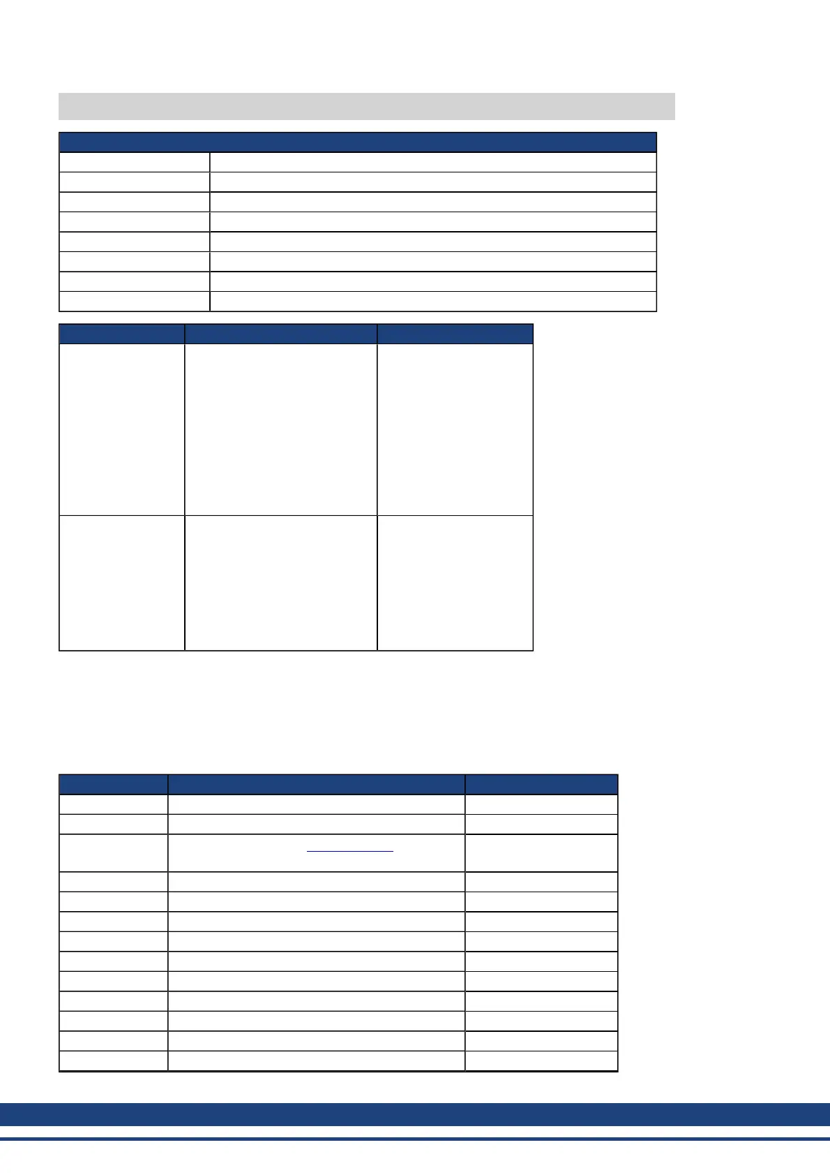
DIN1.MODE TO DIN7.MODE
General Information
Type R/W Parameter
Description Sets the digital input modes.
Units N/A
Range 0 to 22
Default Value 0
Data Type Integer
See Also N/A
Start Version M_01-00-00-000
Fieldbus Index/Subindex Object Start Version
EtherCAT COE
and CANopen
3562h/0 DIN1.MODE
3565h/0 DIN2.MODE
3568h/0 DIN3.MODE
356Bh/0 DIN4.MODE
36F6h/0 DIN5.MODE
36F9h/0 DIN6.MODE
36FCh/0 DIN7.MODE
60FDh/0 DIN1.MODE TO
DIN7.MODE
M_01-00-00-000
Modbus
122 DIN1.MODE
132 DIN2.MODE
142 DIN3.MODE
152 DIN4.MODE
162 DIN5.MODE
172 DIN6.MODE
182 DIN7.MODE
M_01-03-00-000
Description
DIN1.MODE to DIN7.MODE parameters set the functionality of the digital inputs 1 through 7. Digital inputs and
corresponding X7 and X8 pin connectors are described in the AKD Installation Manual, section 8.16.4, Digital
Inputs. The table below summarizes the digital input modes; for detailed descriptions of each mode, see 10.1
Digital Inputs and Outputs.
DINx.MODE Description Task
0 No function; off 0 - None
1 Fault reset 1 - Background
2
Start motion task (use DINx.PARAM for this
task)
2 - 1 KHz
3 Motion task select bit (see Motion Tasks) 3 - Background
4 Motion task start selected (see Motion Tasks) 4 - 1 kHz
5 Start home (see Homing) 5 - Background
6 Start jog 6 - Background
7 Reserved 7 - Background
8 Zero latch 8 - Background
9 Command buffer 9 - Background
10 Control fault relay 10 - Background
11 Home reference 11 - 1 kHz
12 Reserved 12 - None
328 Kollmorgen | December 2010
 Loading...


