VL Parameters
VL.ARPF1 TO VL.ARPF4
General Information
Type R/W Parameter
Description
Sets the natural frequency of the pole (denominator) of anti-resonance
(AR) filters 1, 2, 3, and 4; active in opmodes 1 (velocity) and 2 (position)
only.
Units Hz
Range 5 to 5,000 Hz
Default Value 500 Hz
Data Type Float
See Also
VL.ARPQ1 TO VL.ARPQ4, VL.ARZF1 TO VL.ARZF4, Sets the Q of the
zero (numerator) of anti-resonance filter #1; active in opmodes 1 (velocity)
and 2 (position) only.
Start Version M_01-02-00-000
Fieldbus Index/Subindex Object Start Version
EtherCAT COE
and CANopen
3406h/1 VL.ARPF1
3406h/2 VL.ARPF2
3406h/3 VL.ARPF3
3406h/4 VL.ARPF4
M_01-02-00-000
Modbus
808 VL.ARPF1
810 VL.ARPF2
812 VL.ARPF3
814 VL.ARPF4
M_01-03-00-000
Description
VL.ARPF1 sets the natural frequency of the pole (denominator) of AR filter 1. This value is F
P
in the approximate
transfer function of the filter:
ARx(s) = [s²/(2πF
Z
)² +s/(Q
Z
2πF
Z
) + 1]/ [s²/(2πF
P
)² +s/(Q
P
2πF
P
) + 1]
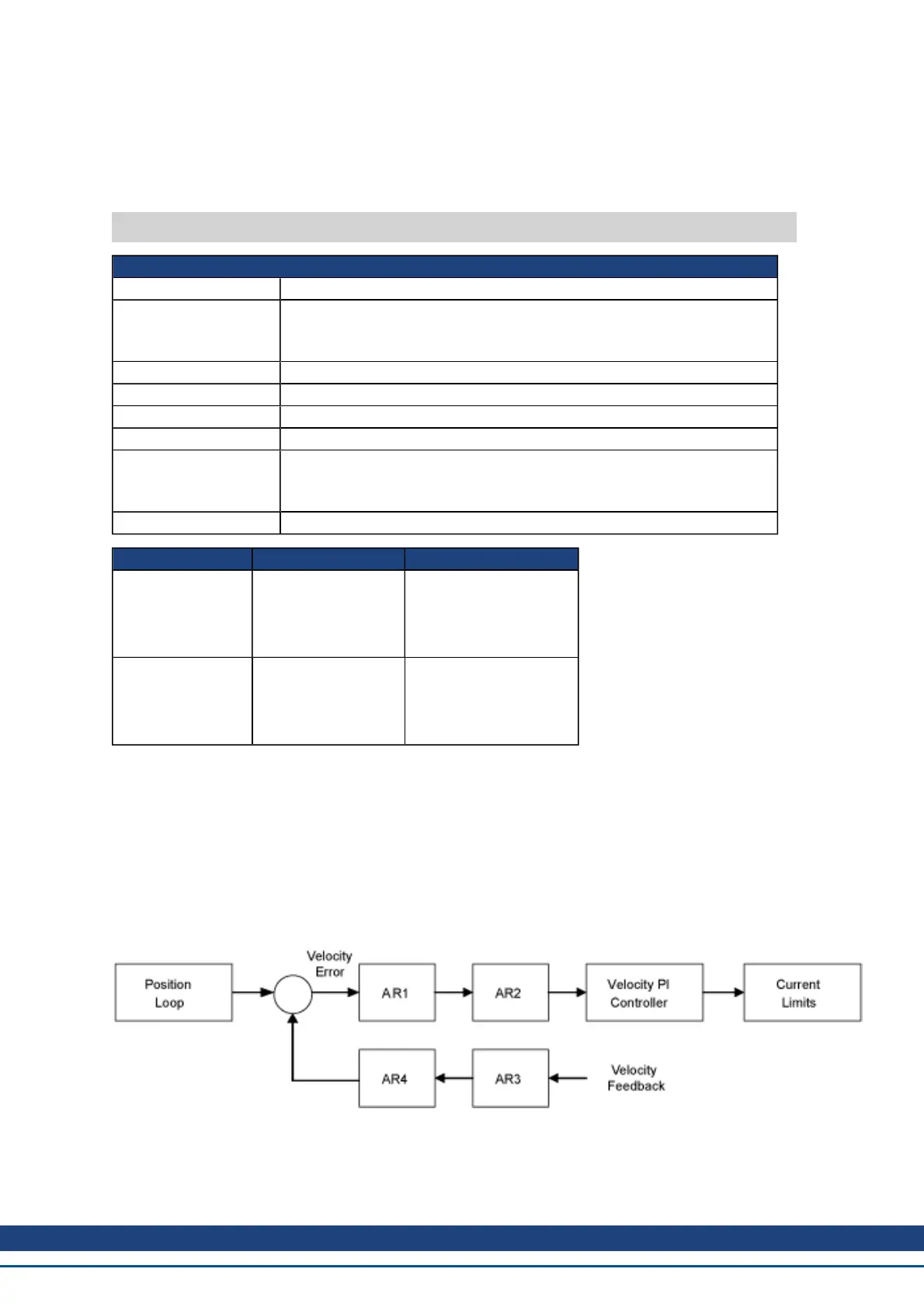
The following block diagram describes the AR filter function; note that AR1 and AR2 are in the forward path,
while AR3 and AR4 are applied to feedback:
AR1, AR2, AR3, and AR4 are used in velocity and position mode, but are disabled in torque mode.
Discrete time transfer function (applies to all AR filters)
AKD User Guide | VL Parameters
Kollmorgen | December 2010 621
 Loading...


