15 Scope
15.1 Overview
The scope allows you to plot up to six different parameters from the drive. Use Full View and Normal View to
toggle between the scope setup (normal) and a larger view of only the scope output (full). You can configure,
save, and restore scope settings from the normal view. The lower right corner of the normal view also includes a
box that indicates status and drive and scope control buttons (Enable Drive, Start Recording, and Refresh).
15.2 Using the Scope
You can set up scope plots using the tabs summarized below:
Tab Function
Channels Select data source, plot axes, and plot appearance.
Time Base and Trigger Select how much data to record and when to start recording the data.
Service Motion Generate basic motion.
Servo Gains Adjust the servo loop gains.
All Gains View all current tuning gains in the drive and manually edit gains.
AR1, AR2, AR3, AR4 Adjust filter settings.
Save and Print
Save the plot as a raw data file or as an image file; email the plot; print the
plot;open the data file in Excel.
Measure Display basic data read from the plots.
Cursors Turn on the cursors and view the data at the cursor positions.
Display Pan, zoom, and control the grid and background color.
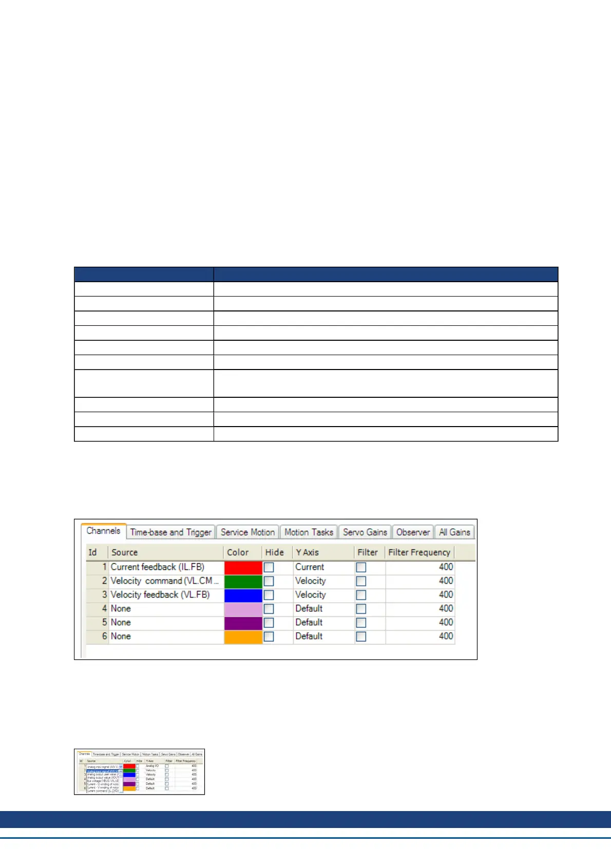
15.2.1 Scope Channels Tab
The Channels tab allows you to select and record up to six channels simultaneously. Select the data to record
for each channel from the lists in the Source, Color, Y-axis, and Filter and Filter Frequency columns. Once a
recording is shown on the scope screen, you can click Hide to remove a channel from the scope display.
15.2.1.1 Source Column
To set a channel to record, click the source you want to set and choose the appropriate channel. You can choose
from None (no data is collected on that channel), preset trace types, or enter a user defined trace. Choosing
“<User Defined>” allows you to record data from pre-defined locations. These locations are provided by the fac-
tory to collect less common values.
AKD User Guide | 15 Scope
Kollmorgen | December 2010 179
 Loading...


