Mode 21: Current Limit
This mode is used to limit the drive current. The current limit is set by a secondary variable; use DINx.PARAM to
set the secondary variable.
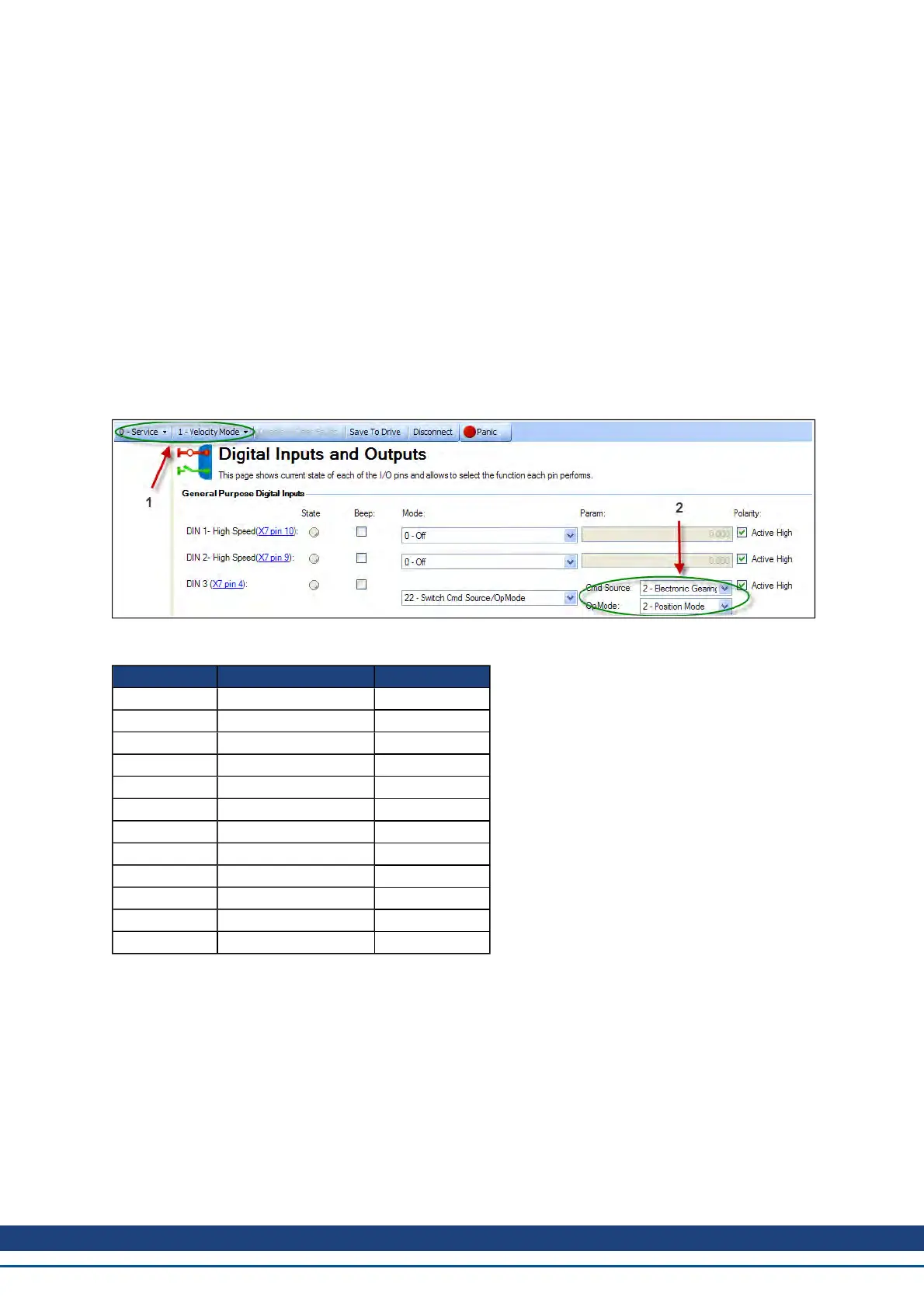
Mode 22: Switch Command Source and Opmode
This modeis used toswitchbetweenthepresent command source/opmodeandanothercommandsource/opmode
settingpredeterminedby theuseruponthelevel changeof a digital input. Arrow 1 inthescreenshot below indicates
thepresent commandsource/opmodethat thedriveis set for. This is themodethedriveis inwhen thedigital input is
not high. This low stateis determinedby theoriginal settings forDRV.CMDSOURCE andDRV.OPMODE.
The drive will switch into the command source/opmode setting shown in arrow 2 when the digital input level
changes to high. This setting is stored by DINx.PARAM and is edited with the drop down boxes at arrow 2.
Note: When the digital input is switched high, the DRV.CMDSOURCE and DRV.OPMODE will take the values
defined by DINx.PARAM. Do not perform a “drive save” in this state, or the low state and high state settings will
become the same.
DINX.PARAM Command Source Opmode
0 0-service 0-torque
1 0-service 1-velocity
2 0-service 2-position
10 1-fieldbus 0-torque
11 1-fieldbus 1-velocity
12 1-fieldbus 2-position
N/A 2-electronic gearing 0-torque
N/A 2-electronic gearing 1-velocity
22 2-electronic gearing 2-position
30 3-analog 0-torque
31 3-analog 1-velocity
32 3-analog 2-position
10.1.4 Digital Outputs
Mode 0-User (Default = 0):The output state is decided by the user or fieldbus.
Mode 1-Mains Ready: The output mode produces a high signal if the drive DC bus voltage is higher than the
under voltage error level and lower than the over voltage error level.
Mode 2-Software Limit: This output turns on when the software limit positions are reached. This output pro-
cudes a high signal if a software limit is reached by traveling in the direction of that software limit. Software limits
are set in the Limits view. In the Limits view, Position 0 is the position limit for negative travel, while Position 1
is the limit for positive travel.
Mode 3-Move Complete: When a motion task has completed its move and the trajectory reaches zero, the
move is considered complete and the output will activate.
AKD User Guide | 10 Configuring General Drive Settings
Kollmorgen | December 2010 87

 Loading...


