AKD User Guide | Connection Diagrams
19.12 DC Bus Link (X3)
The DC bus link can be connected in parallel so that the brake power is divided between all the drives that are
connected to the same DC bus link circuit.
Every drive must have it's own power connection to mains voltage, even if the DC bus link is used.
The drive can be destroyed if DC bus link voltages are different. Only drives with
mains supply from the same mains (identical mains supply voltage) may be con-
nected by the DC bus link. Use unshielded single cores (cross section see page 1 )
with a maximum length of 200 mm. Use shielded cables for longer lengths.
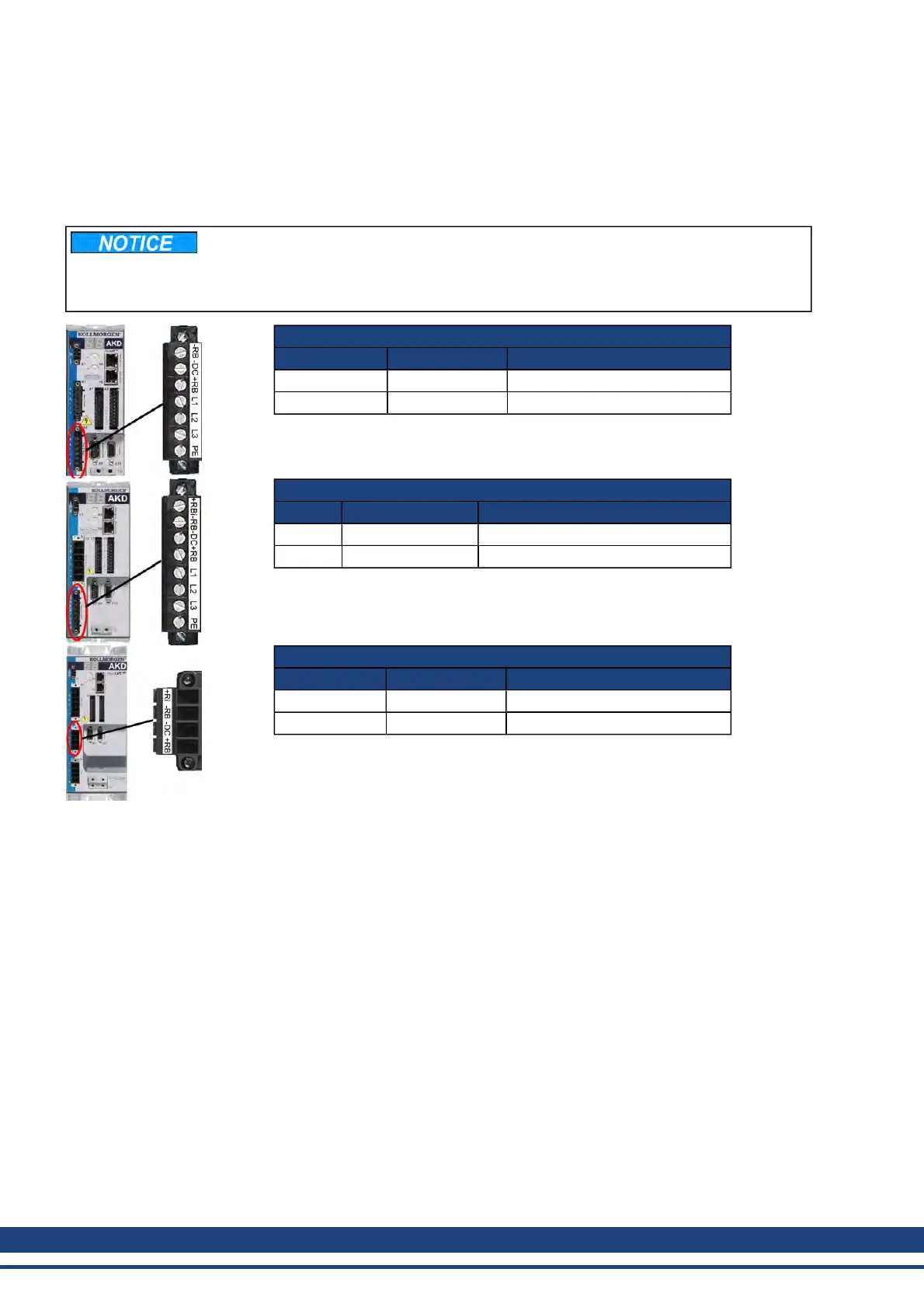
AKD-x00306 to AKD-x00606 (X3)
Pin Signal Description
2 -DC DC-Link Bus negative
3 +DC (+RB) DC-Link Bus positive
AKD-x01206 (X3)
Pin Signal Description
3 -DC DC-Link Bus negative
4 +DC (+RB) DC-Link Bus positive
AKD-x02406 & AKD-xzzz07 (X3)
Pin Signal Description
3 -DC DC-Link Bus negative
4 +DC (+RB) DC-Link Bus positive
236 Kollmorgen | December 2010

 Loading...


