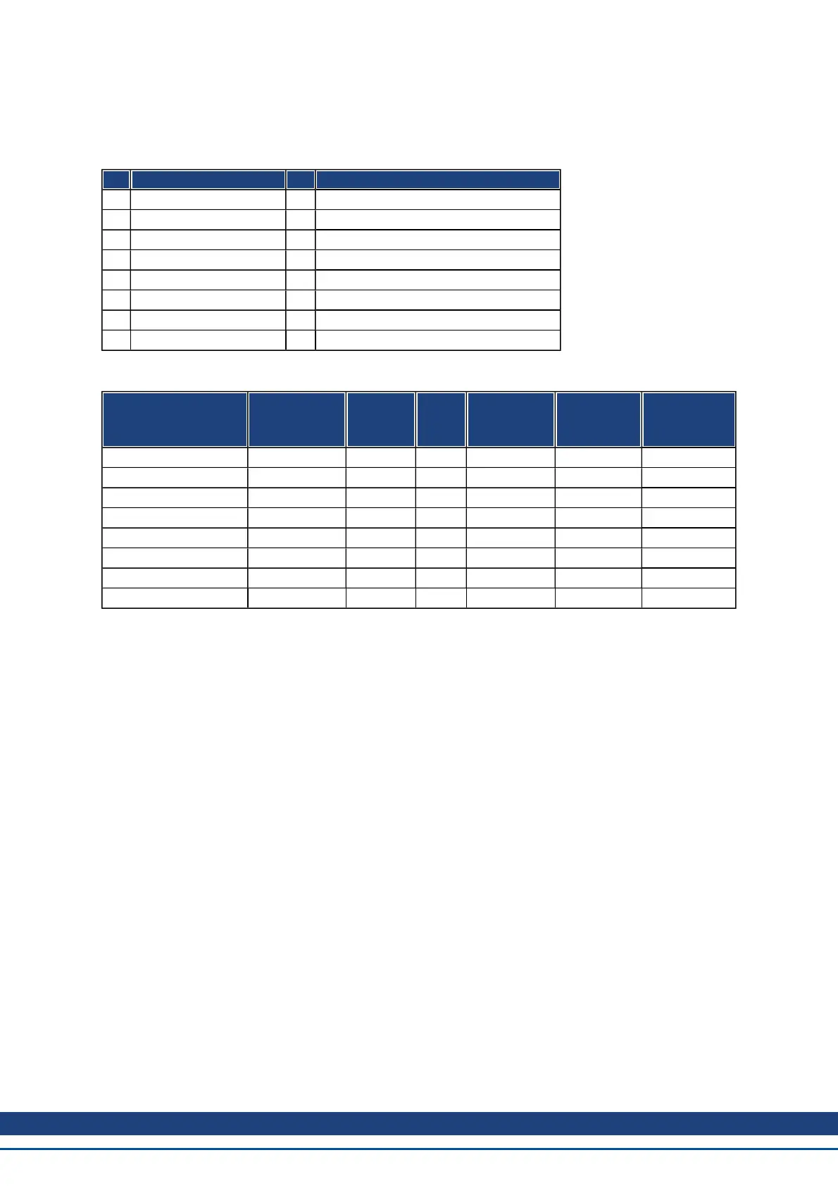
21.4.4.3 Status Machine Bits (status word)
Bit assignment in the status word
Bit Name Bit Name
0 Ready to switch on 8 Manufacturer-specific (reserved)
1 Switched on 9 Remote (always 1)
2 Operation enable 10 Target reached
3 Fault 11 Internal limit active
4 Voltage enabled 12 Operation mode specific (reserved)
5 Quick stop 13 Operation mode specific (reserved)
6 Switch on disabled 14 Manufacturer-specific (reserved)
7 Warning 15 Manufacturer-specific (reserved)
States of the status machine
State
Bit 6
switch on
disable
Bit 5
quick
stop
Bit 3
fault
Bit 2
operation
enable
Bit 1
switched
on
Bit 0
ready to
switch on
Not ready to switch on 0 X 0 0 0 0
Switch on disabled 1 X 0 0 0 0
Ready to switch on 0 1 0 0 0 1
Switched on 0 1 0 0 1 1
Operation enabled 0 1 0 1 1 1
Fault 0 X 1 0 0 0
Fault reaction active 0 X 1 1 1 1
Quick stop active 0 0 0 1 1 1
Bits labeled X are irrelevant. 0 and 1 indicate the status of individual bits.
Description of the remaining bits in the status word
Bit 4: voltage_enabled The DC-link voltage is present if this bit is set.
Bit 7: warning There are several possible reasons for Bit 7 being set and this warning being produced. The rea-
son for this warning can be revealed by using the Object 20subindex manufacturer warnings.
Bit 9: remoteis always set to1, i.e. thedrivecan always communicateandbeinfluencedviatheRS232-interface.
Bit 10: target_reached This is set when the drive has reached the target position.
Bit 11: internal_limit_active This bit specifies that a movement was or is limited. In different modes, different
warnings cause the bit to be set.
AKD User Guide |
Kollmorgen | December 2010 52
 Loading...


