21.4.10 Synchronization
On all drives, the internal PLL is theoretically able to even out an average deviation of up to 4800 ppm in the cycle
time provided by the master. The drive checks once per fieldbus cycle a counter within the drive internal FPGA,
which is cleared by a Sync0 (Distributed clock) event. Depending of the counter value, the drive extends or
decreases the 62.5 µs MTS signal within the drive by a maximum of 300 ns.
The theoretical maximum allowed deviation can be calculated by using the following formula:
The synchronization functionality within the drive can be enabled via setting bit 0 of the FBUS.PARAM02 param-
eter to high. Therefore FBUS.PARAM02 must be set to the value of 1. Furthermore the distributed clock func-
tionality must be enabled by the EtherCAT master in order to activate cyclic Sync0 events.
21.4.10.1 Synchronization behavior with distributed clocks (DC) enabled
When the EtherCAT master enables distributed clocks, a distributed clock (DC) event is created in the AKD
once per fieldbus cycle. An assigned 62.5 µs real-time task in the AKD monitors the elapsed time between the
DC events and the AKD System time and extends or reduces the 62.5 µs strobe to the CPU as necessary.
The following fieldbus parameters are used for the synchronization feature:
1. FBUS.SYNCDIST = Expected time delay of the AKD PLL-code to the DC event.
2. FBUS.SYNCACT = Actual time delay of the AKD PLL-code to the DC event.
3. FBUS.PLLTHRESH = Number of consecutive successful synchronized PLL cycles of the AKD before
the Drive is considered as synchronized.
4. FBUS.SYNCWND = Synchronization window in which the AKD is considered to be synchronized. The
Drive is considered synchronized as long as the following statement is true is true for
FBUS.PLLTHRESH consecutive cycles:
FBUS.SYNCDIST-FBUS.SYNCWND < FBUS.SYNCACT < FBUS.SYNCDIST+FBUS.SYNCWND
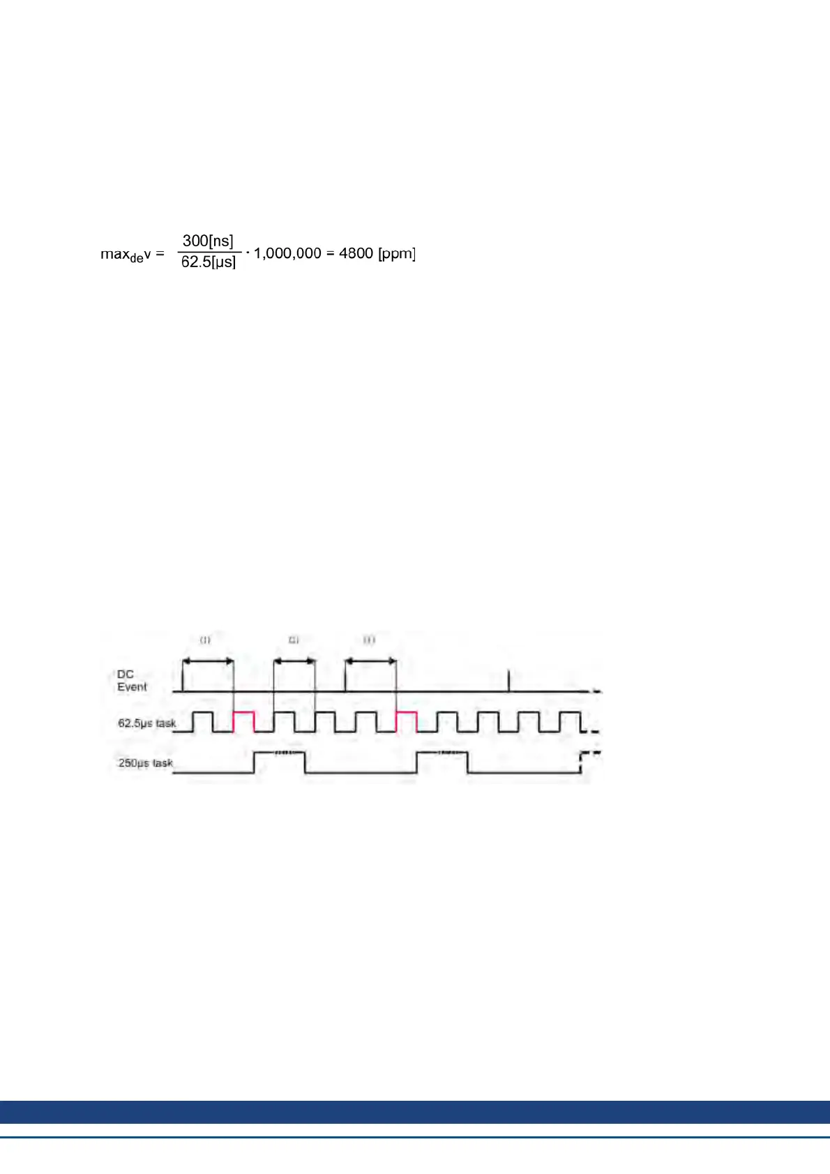
Example with a 4kHz fieldbus sample rate:
Explanation:
The red-marked 62.5[µs] real-time task displays the AKD 62.5 µs real-time task within one fieldbus cycle which
is responsible for calling the AKD PLL-code. The time delay (1) shows the actual delay to the previous DC event,
which is ideally close to the adjusted FBUS.SYNCDIST parameter. Depending on (1) the AKD slightly extends
or reduce the 62.5[µs] IRQ generation of the high-priority real-time task in order to either increase or decrease the
measured time delay to the DC event (1) for the next PLL cycle. The time distance (2) shows the 62.5[µs] ±
x[ms] realtime task of the AKD.
21.4.10.2 Synchronization behavior with distributed clocks (DC) disabled
The AKD fieldbus synchronization algorithm is similar to that used by Distributed Clocks. The difference is that
the AKD synchronizes to a SyncManager2 event instead of the DC event. A SyncManager2 event is created
when the EtherCAT Master sends a new package of command values to the drive while the network is in the
Operational state. This occurs once per fieldbus cycle.
AKD User Guide |
Kollmorgen | December 2010 56
 Loading...


