Error Troubleshooting
Phaser 7100 Service Manual Xerox Internal Use Only2-26
DC330 Component Control
The dc330 Component Control routine is used to test subsystems and discrete components of the
printer. Two component types are defined:
• Inputs: Sensors, Switches, and Motor Encoders.
• Outputs: Motors, Solenoids, Clutches, and Heaters.
Notes:
• A maximum of 8 components (Chain-Link No.) can be registered at the same time.
However, only 1 component can be run at a time.
• Refer to Component Check List (Input) on page 2-28 and Component Check List
(Output) on page 2-31 for specific details of each test.
Component Input/ Run/ Stop
1. Enter Service Diagnostics menu (Entering Service Diagnostics on page 2-14).
2. Press Down Arrow and navigate to Diagnostics Fault Diag.
3. Press Right Arrow and navigate to Fault Diag. DC140 Monitor.
4. Press Down Arrow and navigate to Fault Diag. DC330 Components.
5. Press Right Arrow to display the DC330 Components Component Input.
6. Press Right Arrow to display the Component Input 000-000 screen.
Notes:
• Use Left/ Right Arrow to move the cursor and Up/ Down Arrow to change the number.
• When the cursor is at the left end of the Chain-Link Number, pressing Left Arrow returns
to the DC330 Components Component Input screen at the previous level.
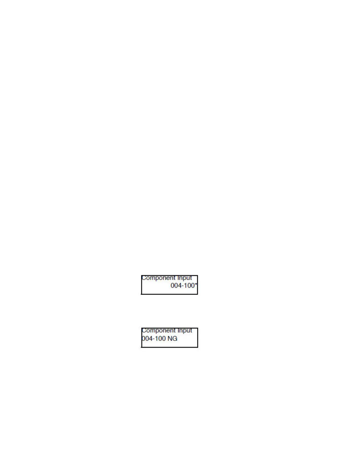
7. Press OK to confirm the Chain-Link Number. An “
*
” appears on the right side of the changed value.
After running a component in step 8 and then stopping the component, other components (up to
8 components) can be registered by repeating steps 6 and 7.
If the Chain-Link Number is not applicable, the NG screen appears. Press OK to return to the
Chain-Link Number input screen.

 Loading...


