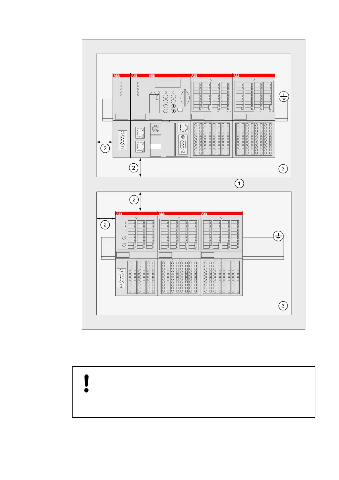
Fig. 214: Installation of AC500/S500 modules in a switch-gear cabinet
1 Cable duct
2 Distance from cable duct ≥20 mm
3 Mounting plate, earthed
NOTICE!
Horizontal mounting is highly recommended.
Vertical mounting is possible, however, derating consideration should be made
to avoid problems with poor air circulation and overheating (see
Ä
Chapter
2.6.1.1 “Environmental Conditions” on page 1248).
System Assembly, Construction and Connection
AC500 (Standard) > Mechanical Dimensions
2019/04/173ADR010121, 13, en_US1254