Functionality
Parameter Value
LED displays For signal states
Internal power supply Via I/O bus
External power supply Not necessary
Electrical Connection
For a detailed description of the mounting, disassembly and electrical connec-
tion of the module, please refer to the System Assembly chapter
Ä
Chapter 2.5
“AC500-eCo” on page 1192.
The electrical connection is carried out by using removable 9-pin and 11-pin terminal blocks.
These terminal blocks differ in their connection system (spring terminals or screw-type termi-
nals, cable mounting from the front or from the side). For more information, refer to Terminal
Blocks for S500-eCo I/O Modules.. The terminal blocks are not included in the module's scope
of delivery and must be ordered separately.
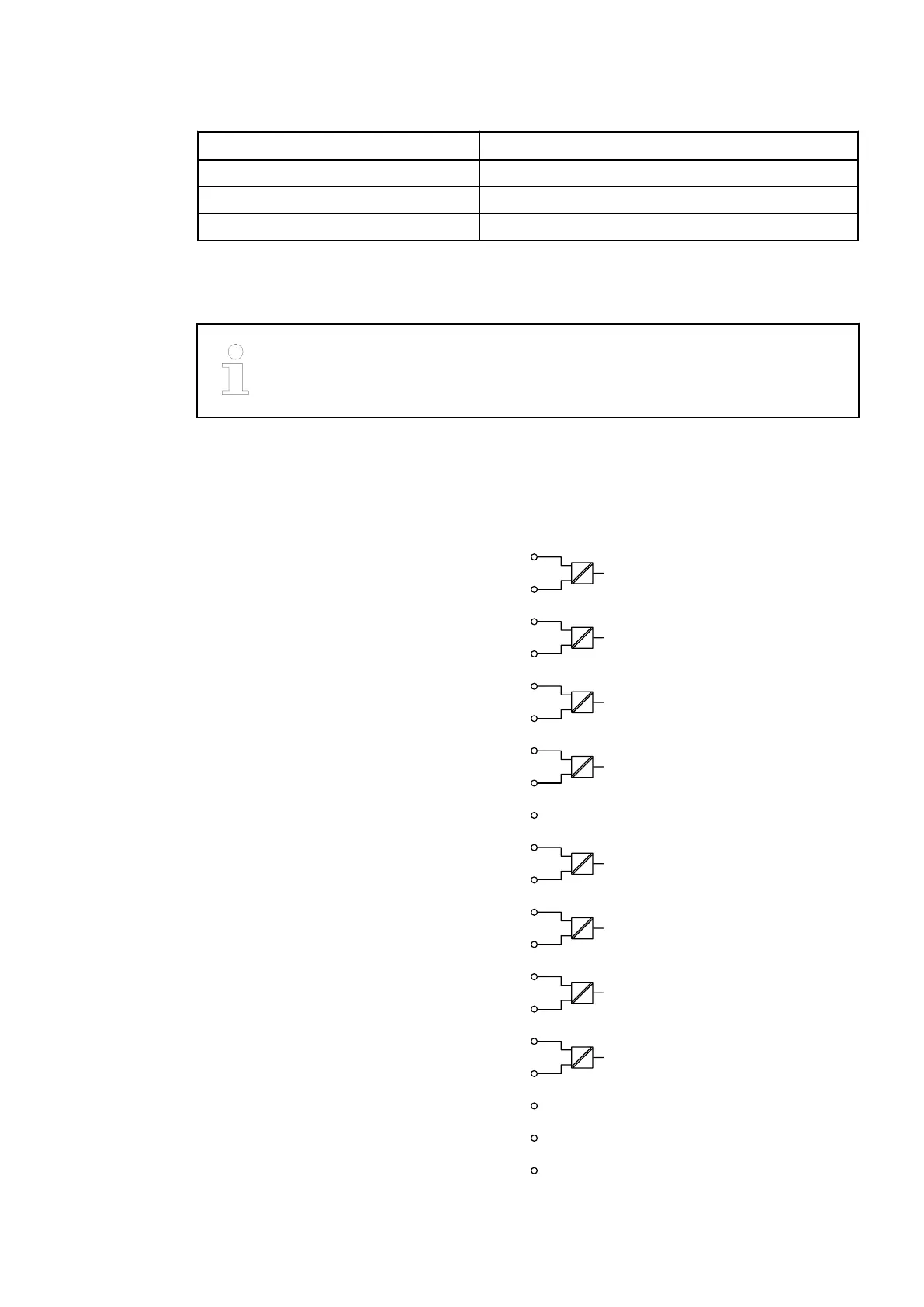
The following block diagram shows the internal construction of the digital inputs:
N0 2
I0 1
N1 4
I1 3
N2 6
I2 5
N3 8
I3 7
N4 11
I4 10
N5 13
I5 12
N6 15
I6 14
N7 17
I7 16
−−− 9
−−− 18
−−− 19
−−− 20
I/O Modules > Digital I/O Modules
2019/04/173ADR010121, 13, en_US206