Voltage -10 V...+10 V Load ±10 mA max. 1 channel used
The function of the LEDs is described under Diagnosis and displays / Displays
Ä
Chapter
1.7.5.1.9 “State LEDs” on page 970.
Unused analog outputs can be left open-circuited.
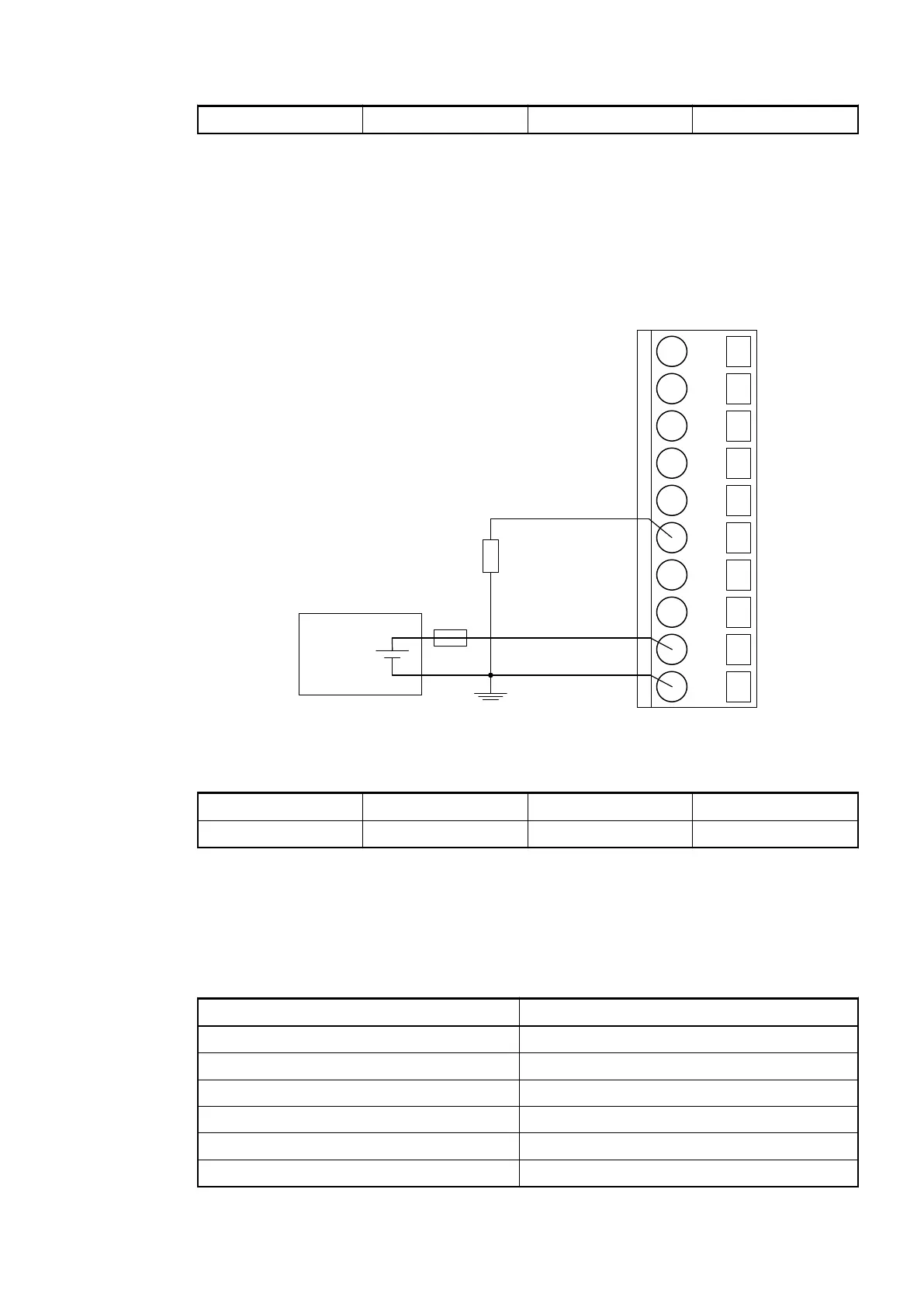
Connection of Analog Output Loads (Current)
The following figure shows the connection of analog output loads (current) to the analog output
AO0. Proceed with the analog output AO1 in the same way.
2.0
AI0+
2.1
AI1+
2.2
AI2+
2.3
AI3+
2.4
AI-
2.5
AO0+
2.6
AO1+
2.7
AO-
2.8
UP
2.9
ZP
24 V DC
-
+
The following measuring ranges can be configured
Ä
Chapter 1.7.5.1.7 “Parameterization”
on page 960 :
Current 0 mA...20 mA Load 0 W...500 W 1 channel used
Current 4 mA...20 mA Load 0 W...500 W 1 channel used
The function of the LEDs is described under Diagnosis and displays / Displays
Ä
Chapter
1.7.5.1.8 “Diagnosis” on page 965.
Unused analog outputs can be left open-circuited.
1.7.5.1.4 Internal Data Exchange
Parameter Value
Digital inputs (bytes) 3
Digital outputs (bytes) 3
Analog inputs (words) 4
Analog outputs (words) 2
Counter input data (words) 4
Counter output data (words) 8
Communication Interface Modules (S500) > PROFIBUS
2019/04/17 3ADR010121, 13, en_US 959