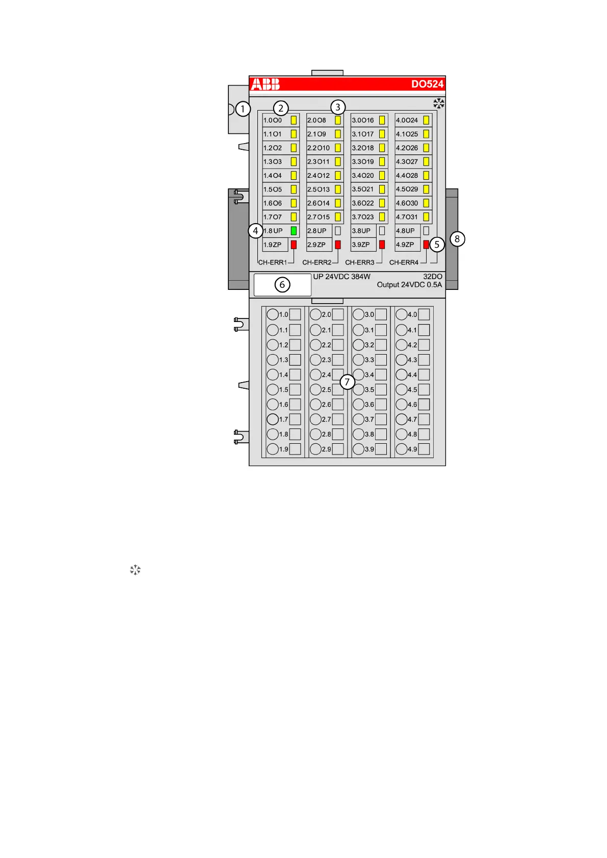
EasyManuals Logo

ABB AC500 PLC User Manual

ABB AC500 PLC
1315 pages
To Next Page IconTo Next Page
To Previous Page IconTo Previous Page
Page #353 background imageLoading...
Page #353 background image
1 I/O bus
2 Allocation between terminal number and signal name
3 32 yellow LEDs to display the signal states at the digital outputs (O0 - O31)
4 1 green LED to display the state of the process supply voltage UP
5 4 red LEDs to display errors
6 Label
7 Terminal unit
8 DIN rail
Sign for XC version
Intended Purpose
The device can be used as a decentralized I/O extension module for S500 Communication
Interface Modules (e. g. CI592-CS31, CI501-PNIO, CI541-DP, CI581-CN) or as a centralized
extension module for AC500 CPUs (PM5xx).
The outputs are electrically isolated from all other circuitry of the module. There is no potential
separation between the channels.
Device Specifications
I/O Modules > Digital I/O Modules
2019/04/17 3ADR010121, 13, en_US 353

Table of Contents

Questions and Answers:

Question and Answer IconNeed help?

Do you have a question about the ABB AC500 PLC and is the answer not in the manual?

ABB AC500 PLC Specifications

General IconGeneral
Digital InputsUp to 1024
Digital OutputsUp to 1024
Real-time clockYes
Power Supply24 V DC
Protection ClassIP20
ProcessorARM based
Programming LanguagesIEC 61131-3 (LD, ST, FBD, SFC, IL)
Operating Temperature-25°C to +70°C
Communication InterfacesEthernet, CAN, RS-232, RS-485

Related product manuals