Current 0 mA...20 mA 1 channel used
Current 4 mA...20 mA 1 channel used
Unused input channels can be left open-circuited, because they are of low resistance.
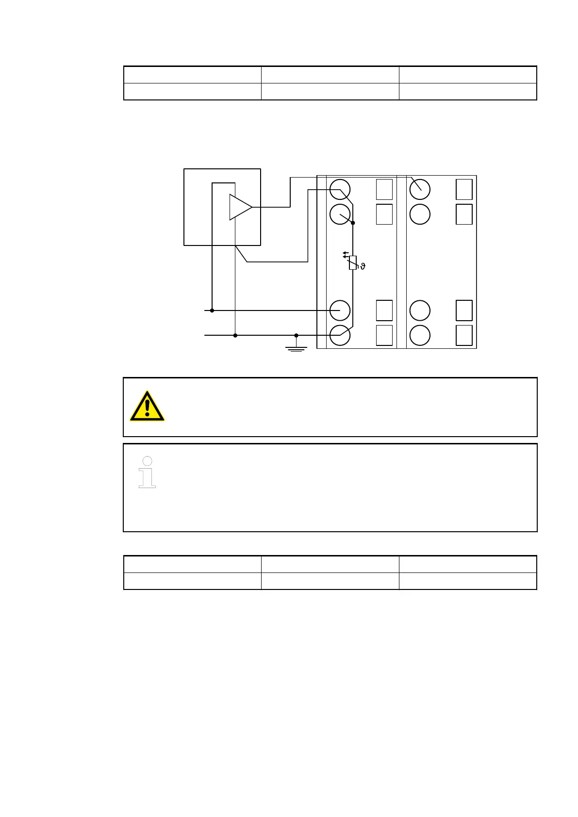
Connection of Active-type Analog Sensors (Voltage) with no Electrically Isolated Power Supply
UP
ZP
1.0
I0-
1.1
I1-
1.8
UP
1.9
ZP
PTC
2.0
I0+
2.1
I1+
2.8
UP
2.9
ZP
0 ... 10 V
AGND
Fig. 64: Connection example
CAUTION!
The potential difference between AGND and ZP at the module must not be
greater than 1V, not even in case of long lines (see figure Terminal Assignment).
If AGND does not get connected to ZP, the sensor current flows to ZP via the
AGND line. The measuring signal is distorted, as a very small current flows
through the voltage line. The total current through the PTC should not exceed
50 mA. This measuring method is therefore only suitable for short lines and
small sensor currents. If there are bigger distances, the difference measuring
method should be applied.
Voltage 0 V...10 V 1 channel used
Voltage -10 V...+10 V *) 1 channel used
*) if the sensor can provide this signal range
In order to avoid error messages or long processing times, it is useful to configure unused
analog input channels as "unused".
I/O Modules > Analog I/O Modules
2019/04/17 3ADR010121, 13, en_US 527