1.0
1.1
1.8
1.9
AI0+
AI1+
UP
ZP
UP
ZP
PTC
1.5
AI–
1
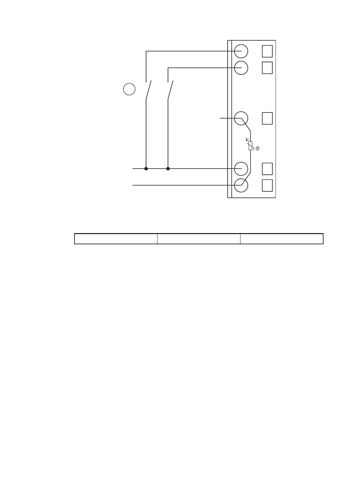
Fig. 167: Use of analog inputs as digital inputs
1 1 digital signal requires 1 channel
Digital input 24 V 1 channel used
The measuring ranges are described in the section Measuring Ranges
Ä
Chapter 1.7.3.1.7
“Parameterization” on page 842
Ä
Chapter 1.7.3.1.10 “Measuring Ranges” on page 851.
Connection of Analog Output Loads (Voltage, Current)
The following figure shows the connection of analog output loads (voltage, current).
Communication Interface Modules (S500) > EtherCAT
2019/04/17 3ADR010121, 13, en_US 839