CAUTION!
Risk of damaging the processor module!
– Never short-circuit or overload the outputs.
– Never connect inductive loads without an external suppression against
voltage peaks due to inductive kickback.
– Never connect voltages > 240 V. All outputs must be fed from the same
phase.
– Use an external 5 A fast protection fuse for the outputs.
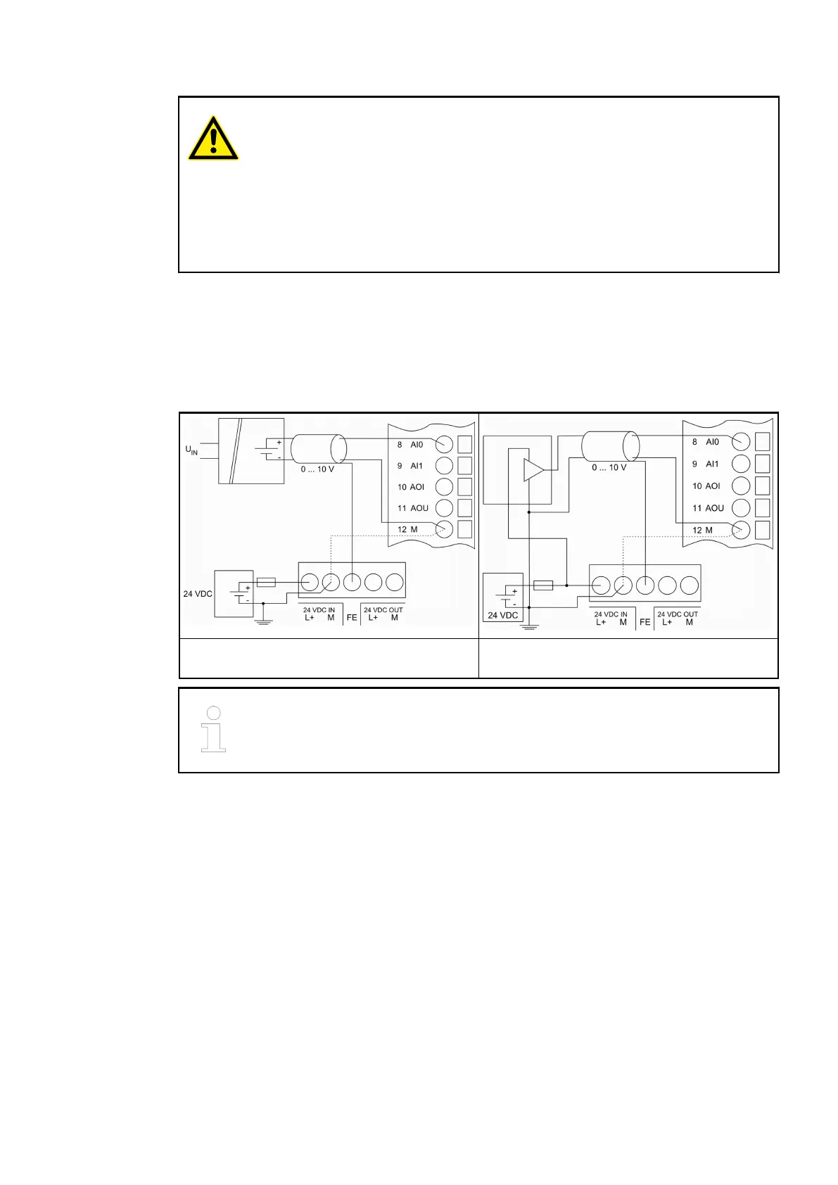
Connection of the Analog Inputs
The following figures show an example of the electrical connection of analog sensors (voltage)
to the input AI0 of PM56x processor modules. Proceed with the input AI1 in the same way:
Connection of active-type analog sensors
(voltage)
Connection of passive-type analog sensors
(voltage)
The inputs AI0 and AI1 must be configured as analog inputs.
Connection of the Analog Output
The following figures show the electrical connection of analog actuators (voltage and current) to
the output AO of PM56x processor modules:
Processor Modules > AC500-eCo
2019/04/173ADR010121, 13, en_US56