2.0
AI0+
2.1
AI1+
2.2
AI2+
2.3
AI3+
2.4
AI-
2.5
AO0+
2.6
AO1+
2.7
AO-
2.8
UP
2.9
ZP
24 V DC
-
+
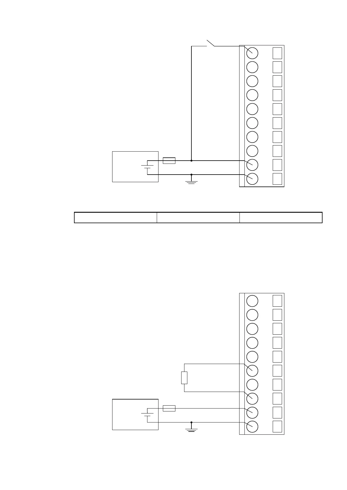
Fig. 126: Use of analog inputs as digital inputs
Digital input 24 V 1 channel used
For the measuring ranges that can be configured, please refer to the sections Measuring
Ranges
Ä
Chapter 1.7.1.2.10 “Measuring Ranges” on page 731 and Parameterization
Ä
Chapter 1.7.1.2.7 “Parameterization” on page 721.
Connection of Analog Output Loads (Voltage)
The following figure shows the connection of output loads to the analog output AO0. Proceed
with the analog output AO1 in the same way.
2.0
AI0+
2.1
AI1+
2.2
AI2+
2.3
AI3+
2.4
AI-
2.5
AO0+
2.6
AO1+
2.7
AO-
2.8
UP
2.9
ZP
24 V DC
-
+
Fig. 127: Connection of analog output loads (voltage)
Communication Interface Modules (S500) > CANopen
2019/04/17 3ADR010121, 13, en_US 719