Technical Data
The System Data of AC500 and S500
Ä
Chapter 2.6.1 “System Data AC500” on page 1248 are
valid for standard version.
The System Data of AC500-XC
Ä
Chapter 2.7.1 “System Data AC500-XC” on page 1309 are
valid for the XC version.
Only additional details are therefore documented below.
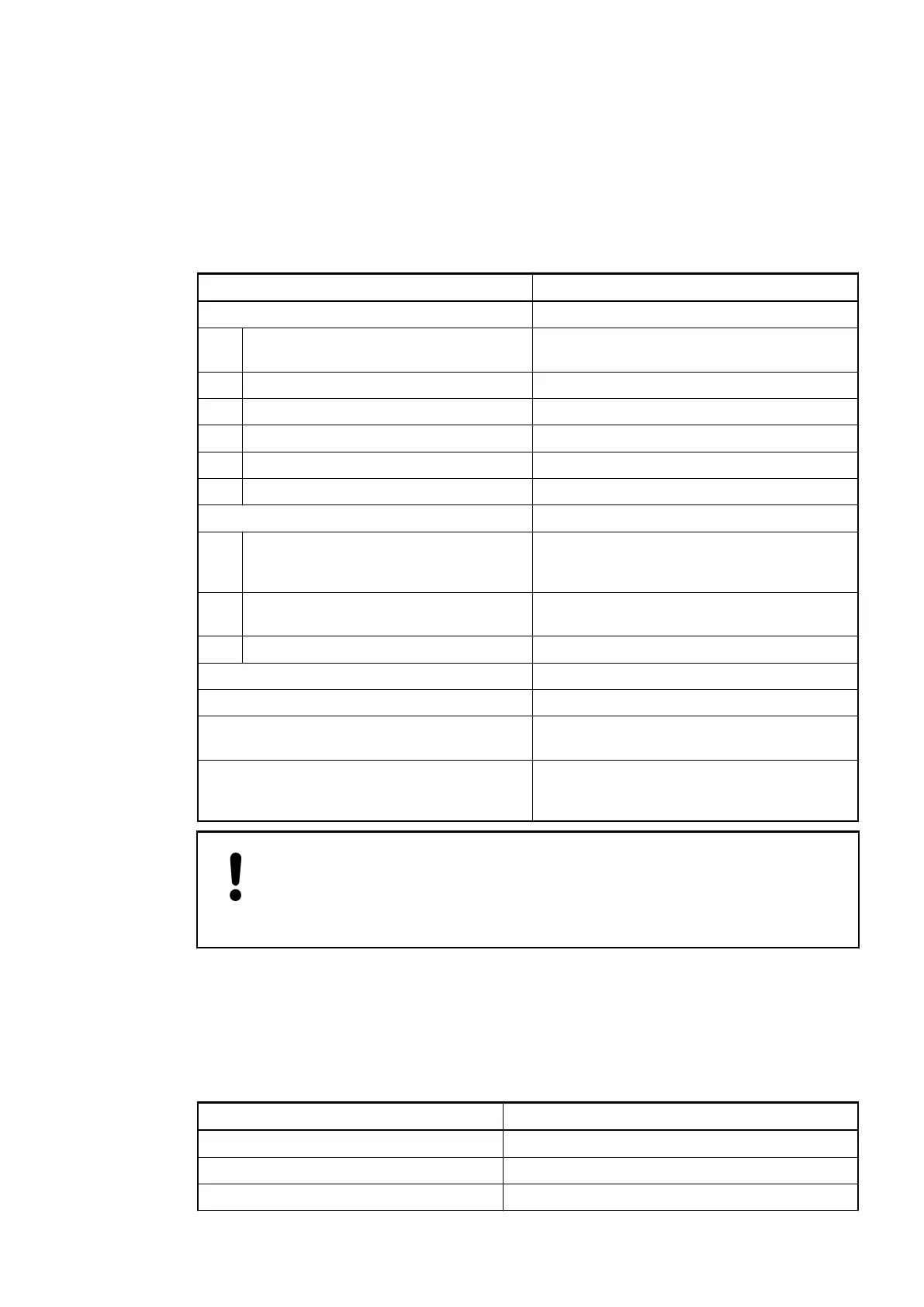
Parameter Value
Process supply voltage UP
Connections Terminals 1.8, 2.8, 3.8 and 4.8 for +24 V (UP)
as well as 1.9, 2.9, 3.9 and 4.9 for 0 V (ZP)
Rated value 24 VDC
Max. ripple 5 %
Protection against reversed voltage Yes
Rated protection fuse on UP 10 A fast
Galvanic isolation Yes, per module
Current consumption
From 24 VDC power supply at the termi-
nals UP/L+ and ZP/M of the CPU/Bus
Module
ca. 2 mA
From UP at normal operation / with out-
puts
0.05 A + output loads
Inrush current from UP (at power up) 0.010 A²s
Max. power dissipation within the module 6 W (outputs OFF)
Weight (without terminal unit) ca. 300 g
Mounting position Horizontal or vertical with derating (output
load reduced to 50 % at 40 °C per group)
Cooling The natural convection cooling must not be
hindered by cable ducts or other parts in the
switch-gear cabinet.
NOTICE!
Attention:
All I/O channels (digital and analog) are protected against reverse polarity,
reverse supply, short circuit and continuous overvoltage up to 30 VDC.
No effects of multiple overloads on isolated multi-channel modules occur, as every channel is
protected individually by an external fuse.
Technical Data of the Digital Inputs
Parameter Value
Number of channels per module 8
Distribution of the channels into groups 1 group of 8 channels
Terminals of the channels I0 to I7 1.0 to 1.7
No effects of
multiple over-
loads
I/O Modules > Digital I/O Modules
2019/04/173ADR010121, 13, en_US380