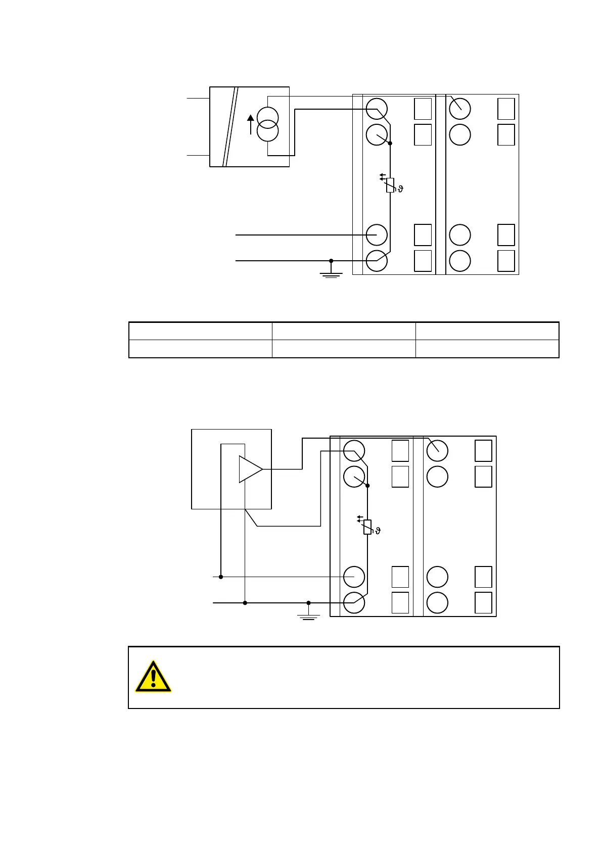
Connection of Active-type Analog Sensors (Current) with Electrically Isolated Power Supply
UP
ZP
1.0
I0-
1.1
I1-
1.8
UP
1.9
ZP
PTC
2.0
I0+
2.1
I1+
2.8
UP
2.9
ZP
U
IN
0 ... +20 mA
+4 ... +20 mA
+
-
Fig. 73: Connection example
Current 0 mA...20 mA 1 channel used
Current 4 mA...20 mA 1 channel used
Unused input channels can be left open-circuited, because they are of low resistance.
Connection of Active-type Analog Sensors (Voltage) with no Electrically Isolated Power Supply
UP
ZP
1.0
I0-
1.1
I1-
1.8
UP
1.9
ZP
PTC
2.0
I0+
2.1
I1+
2.8
UP
2.9
ZP
0 ... 10 V
AGND
Fig. 74: Connection example
CAUTION!
The potential difference between AGND and ZP at the module must not be
greater than 1V, not even in case of long lines (see figure Terminal Assignment).
I/O Modules > Analog I/O Modules
2019/04/17 3ADR010121, 13, en_US 551