Do not connect any voltages externally to digital outputs!
This ist not intended usage.
Reason: Externally voltages at one or more terminals DC0...DC7 or DO0...DO7
may cause that other digital outputs are supplied through that voltage instead of
voltage UP3 (reverse voltage).
This is also possible, if DC channels are used as inputs. For this, the source for
the input signals should be the impressed UP3 of the device.
This limitation does not apply for the input channels DI0...DI7.
CAUTION!
Risk of malfunction by not intended usage!
If the function cut off of the digital outputs should be used by deactivation of the
supply voltage UP3, be sure that no external voltage is conncted at the outputs
DO0...DO7 and DC0...DC7.
Possibilities of Connection
Mounting on terminal units TU509 or TU510:
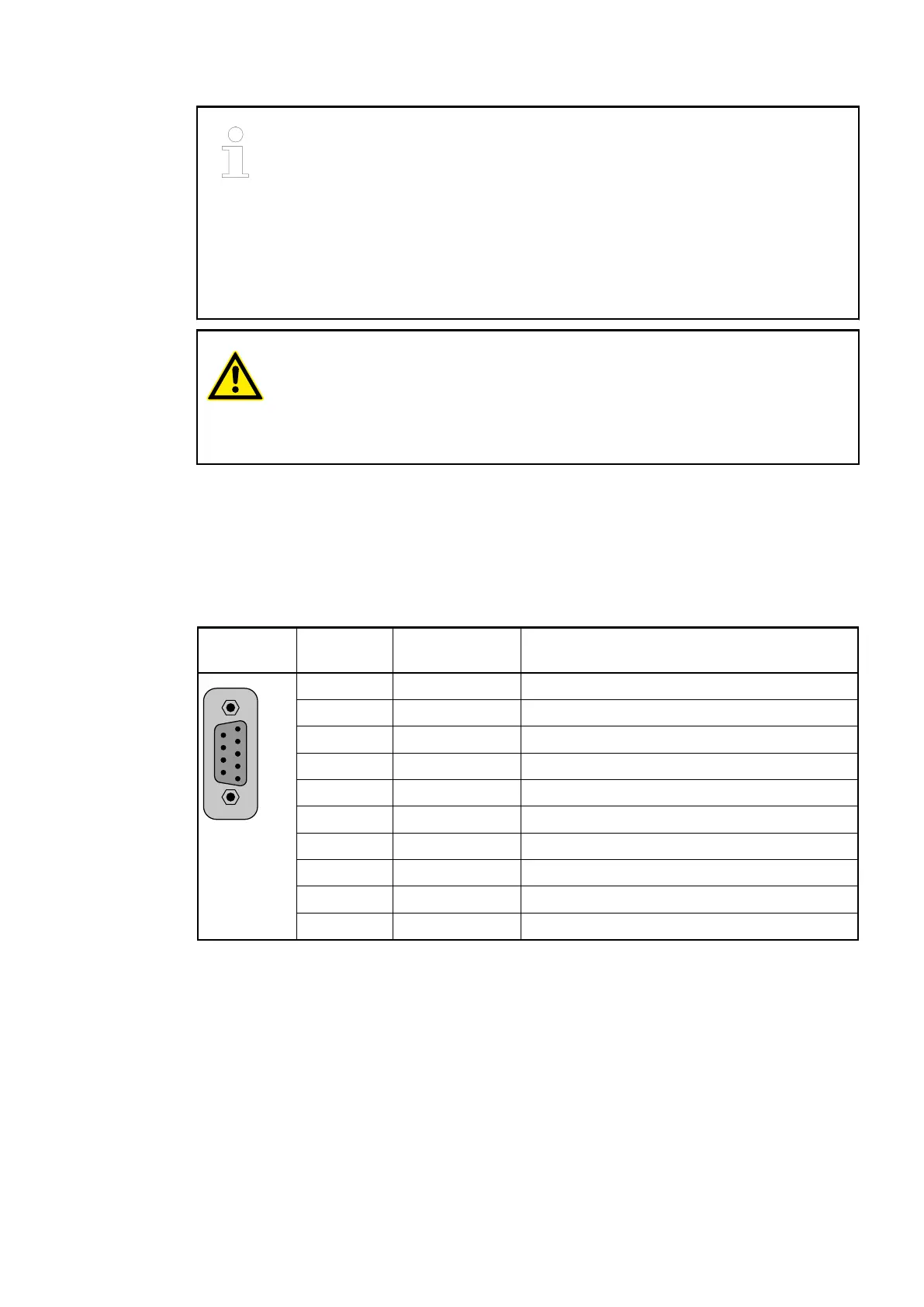
The assignment of the 9-pole female D-SUB connector for the PROFIBUS DP signals.
Serial Inter-
face
Pin Signal Description
1 --- Reserved
2 --- Reserved
3 B PROFIBUS DP signal B
4 --- Reserved
5 DGND Ground for 5 V power supply
6 VP (5 V) 5 V power supply
7 --- Reserved
8 A PROFIBUS DP signal A
9 --- Reserved
Shield Cable shield Functional earth
Bus Termination
The line ends of the bus segment must be equipped with bus termination resistors. Normally,
these resistors are integrated in the interface connectors.
Communication Interface Modules (S500) > PROFIBUS
2019/04/17 3ADR010121, 13, en_US 983