3
)
With "Module" the following allocation applies:
31 = Module itself; 1...7 = Expansion 1...7
4
)
In case of module errors, with channel "31 = Module itself" is output.
5
)
Ch = 14...21 indicates the digital inputs/outputs DC8...DC15
6
)
Ch = 8...11 indicates the analog inputs AI0...AI3
7
)
Ch = 12...13 indicates the analog outputs AO0...AO1
1.7.2.2.10 State LEDs
The LEDs are located at the front of module. There are 2 different groups:
● The 4 system LEDs (PWR, CS31, S-ERR and I/O-Bus) show the operation state of the
module and display possible errors.
● The 26 process LEDs (UP, inputs, outputs, CH-ERR2 to CH-ERR4) show the process
supply voltage and the states of the inputs and outputs and display possible errors.
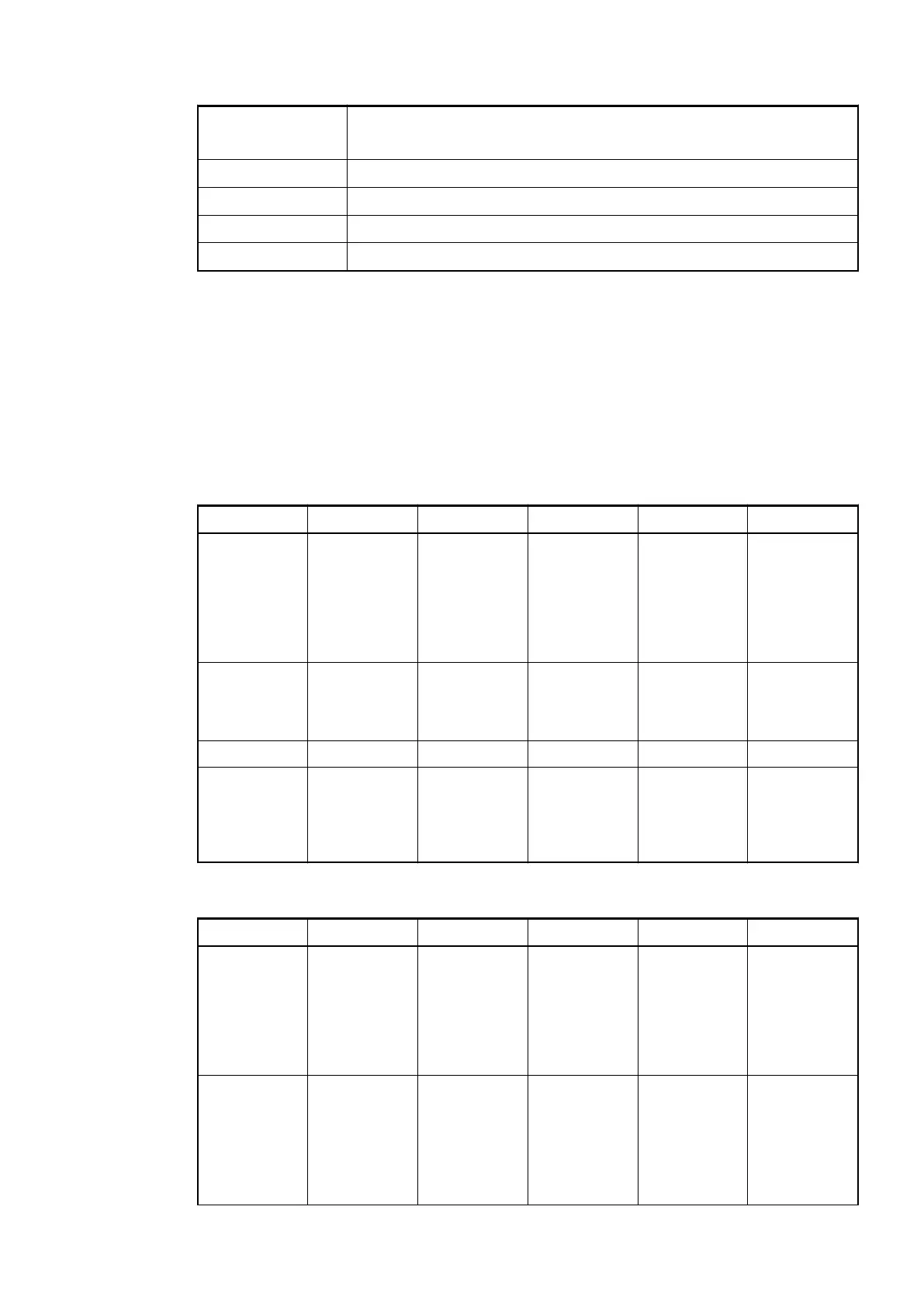
Table 126: State of the 4 System-LEDs:
LED State Color OFF ON Flashing
PWR/RUN System
voltage
Green Process
supply voltage
missing
Internal
supply voltage
OK, module
ready for com-
munication
with IO Con-
troller
Start-up / pre-
paring com-
munication
CS31 CS31 commu-
nication
Green No communi-
cation at the
CS31 bus
module
Communica-
tion at the
CS31 bus OK
Diagnosis
mode
S-ERR Sum Error Red No error Internal error --
I/O-Bus Communica-
tion via the
I/O-Bus
Green No expansion
modules con-
nected or
communica-
tion error
Expansion
modules con-
nected and
operational
---
Table 127: State of the 27 Process LEDs:
LED State Color OFF ON Flashing
DI0 to DI7 Digital input Yellow Input is OFF Input is ON
(the input
voltage is
even dis-
played if the
supply voltage
is OFF)
--
DC8 to DC15 Digital input/
output
Yellow Input/output is
OFF
Input/output is
ON (the input
voltage is
even dis-
played if the
supply voltage
is OFF)
--
Communication Interface Modules (S500) > CS31
2019/04/17 3ADR010121, 13, en_US 801