NOTICE!
Risk of malfunctions!
Unused slots for communication modules are not protected against accidental
physical contact.
– Unused slots for communication modules must be covered with dummy
communication modules (TA524
Ä
Chapter 1.8.2.3 “TA524 - Dummy Com-
munication Module” on page 1151 to achieve IP20 rating.
– I/O bus connectors must not be touched during operation.
1.1.2.2 Electrical Connection
The electrical connection is set up using the terminals of the TF5x1-CMS.
Mounting, disassembling and electrical connection for the terminal function
block and the I/O modules are described in the system assembly chapter, as
well as the serial I/O bus
Ä
Chapter 2.4 “Overall Information (valid for complete
AC500 Product Family)” on page 1178.
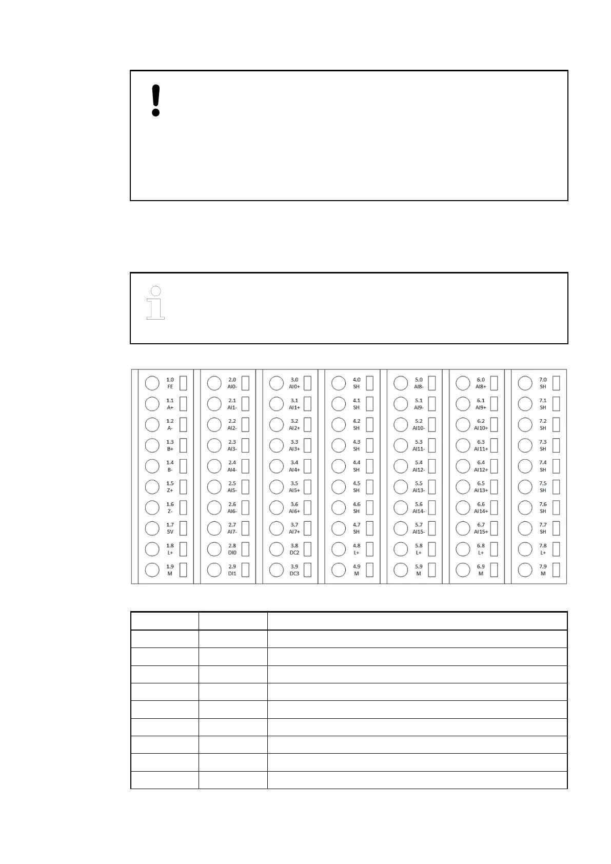
Terminal Signal Description
1.0 FE Functional earth for encoder shield connection
1.1 A+ Input signal A of encoder 0
1.2 A- Inverted input signal A of encoder 0
1.3 B+ Input signal B of encoder 0
1.4 B- Inverted input signal B of encoder 0
1.5 Z+ Input signal Z of encoder 0
1.6 Z- Inverted input signal Z of encoder 0
1.7 5 V +5 VDC power supply output for encoder
1.8 L+ Process voltage L+ (24 VDC)
Terminal assign-
ment of the
TF5x1-CMS
Terminal Bases (AC500 Standard) > TF501-CMS and TF521-CMS - Function Module Terminal Bases
2019/04/17 3ADR010121, 13, en_US 15