Functionality
8 analog inputs, individually configurable for
● Unused (default setting)
● 0 V...5 V, 0 V...10 V
● -50 mV...+50 mV, -500 mV...+500 mV
● -1 V...+1 V, -5 V...+5 V, -10 V...+10 V
● 0 mA...20 mA
● 4 mA...20 mA
● -20 mA...20 mA
● Pt100, -50 °C...+70 °C or 400 °C (2-, 3- and 4-wire)
● Pt100, -200 °C...+850 °C (2-, 3- and 4-wire)
● Pt1000, -50 °C...+400 °C (2-, 3- and 4-wire)
● Ni1000, -50 °C...+150 °C (2-, 3- and 4-wire)
● Cu50 (1.426): -50 °C...+200 °C (2-, 3- and 4-wire)
● Cu50 (1.428): -200 °C...+200 °C (2-, 3- and 4-wire)
● 0 Ω...50 kΩ
● Thermocouples of types J, K, T, N, S
● Resistance measuring bridge
● Digital signals (digital input)
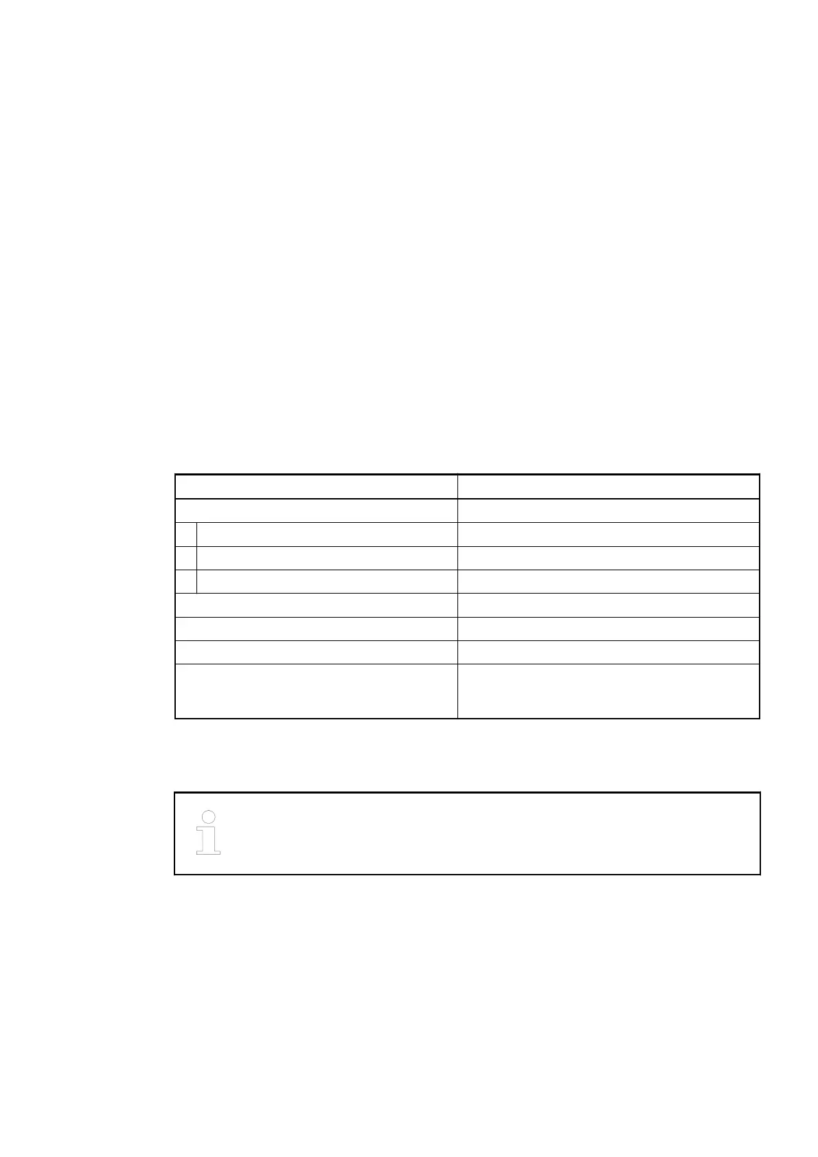
Parameter Value
Resolution of the analog channels
Voltage and current, bipolar 15 bits plus sign
Voltage and current, unipolar 15 bits
Temperature 0.1 °C (0,01°C at Pt100 -50 °C...+70 °C)
LED displays 11 LEDs for signals and error messages
Internal power supply through the expansion bus interface (I/O bus)
External power supply via terminals (process voltage UP = 24 VDC)
Required terminal unit
TU515 or TU516
Ä
Chapter 1.4.3 “TU515,
TU516, TU516-H and TU542 for I/O Modules”
on page 153
Electrical Connection
For a detailed description of the mounting, disassembly and electrical connec-
tion of the module, please refer to the System Assembly, Construction and Con-
nection chapter
Ä
Chapter 2.6 “AC500 (Standard)” on page 1248.
The modules are plugged on an I/O terminal unit
Ä
Chapter 1.4.3 “TU515, TU516, TU516-H
and TU542 for I/O Modules” on page 153. Properly position the modules and press until they
lock in place. The terminal units are mounted on a DIN rail or with 2 screws plus the additional
accessory for wall mounting (TA526
Ä
Chapter 1.8.2.4 “TA526 - Wall Mounting Accessory”
on page 1152).
The electrical connection of the I/O channels is carried out using the 40 terminals of the I/O ter-
minal unit. I/O modules can be replaced without re-wiring the terminal units.
I/O Modules > Analog I/O Modules
2019/04/17 3ADR010121, 13, en_US 473