FE
R1
R2
B1
B2
FE
B1
B2
FE
UP
ZP
1.0
1.1
1.2
1.3
1.4
1.5
1.6
1.7
1.8
1.9
CS31 Bus-end
1.0
1.1
1.2
1.3
1.4
1.5
1.6
1.7
1.8
1.9
+5V
1.0
1.1
1.2
1.3
1.4
1.5
1.6
1.7
1.8
1.9
1.0
1.1
1.2
1.3
1.4
1.5
1.6
1.7
1.8
1.9
CS31 Bus-endCS31 bus end
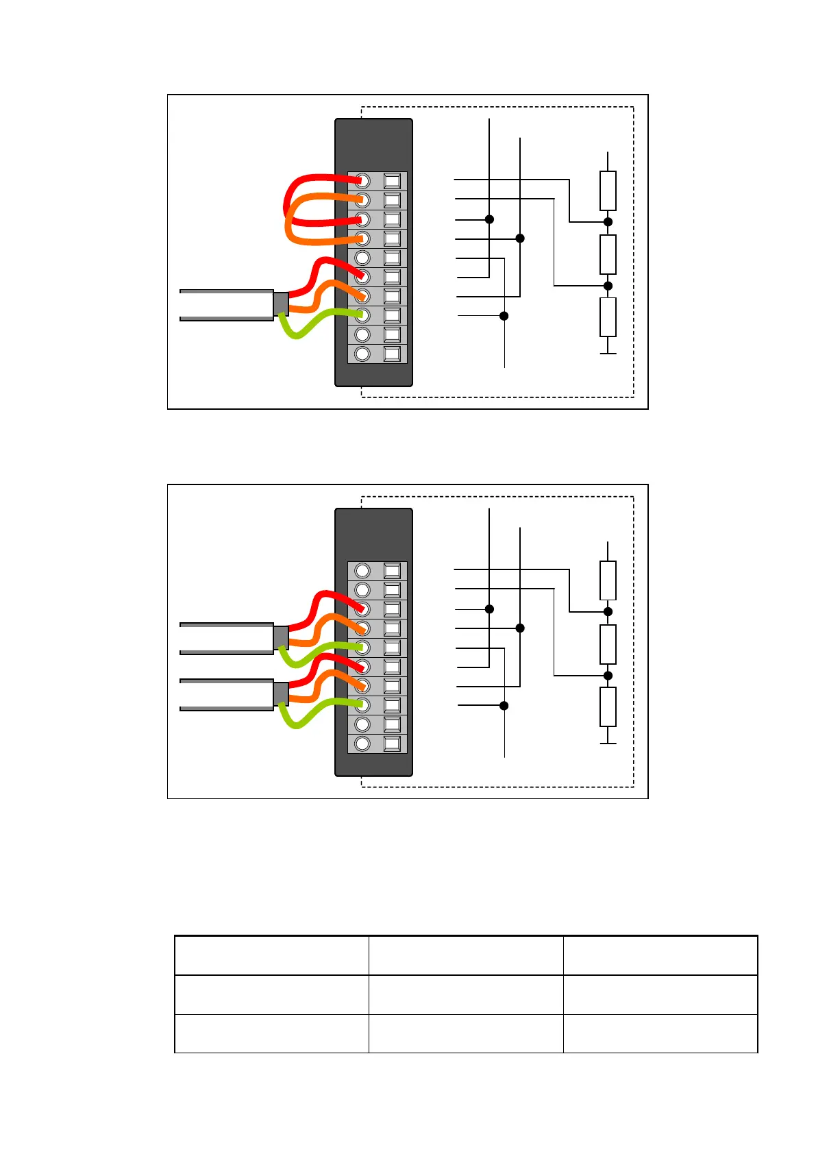
Fig. 157: CS31 bus module at the end of the CS31 Bus
The following figure shows a CS31 Bus module in the middle of a CS31 Bus (end-of-line
resistor not activated).
F E
R1
R2
B 1
B 2
F E
B 1
B 2
F E
UP
Z P
1 . 0
1 . 1
1 . 2
1 . 3
1 . 4
1 . 5
1 . 6
1 . 7
1 . 8
1 . 9
C S 31 B us-e nd
1 . 0
1 . 1
1 . 2
1 . 3
1 . 4
1 . 5
1 . 6
1 . 7
1 . 8
1 . 9
+ 5 V
1 . 0
1 . 1
1 . 2
1 . 3
1 . 4
1 . 5
1 . 6
1 . 7
1 . 8
1 . 9
1 . 0
1 . 1
1 . 2
1 . 3
1 . 4
1 . 5
1 . 6
1 . 7
1 . 8
1 . 9
C S 31 B us-e ndC S 31 bus out
C S 31 B us-e ndC S 31 B us-e ndC S 31 bus in
Fig. 158: CS31 Bus module in the middle of the CS31 Bus
Details on CS31 wiring is described seperately
Ä
Chapter 2.6.4.8 “CS31 System Bus”
on page 1282.
1.7.2.3.5 Internal Data Exchange
without the Fast Counter with the Fast Counter (only
with AC500)
Digital inputs (bytes) 3 + expansion modules (see
above)
5 + expansion modules (see
above)
Digital outputs (bytes) 2 + expansion modules (see
above)
4 + expansion modules (see
above)
Communication Interface Modules (S500) > CS31
2019/04/17 3ADR010121, 13, en_US 815