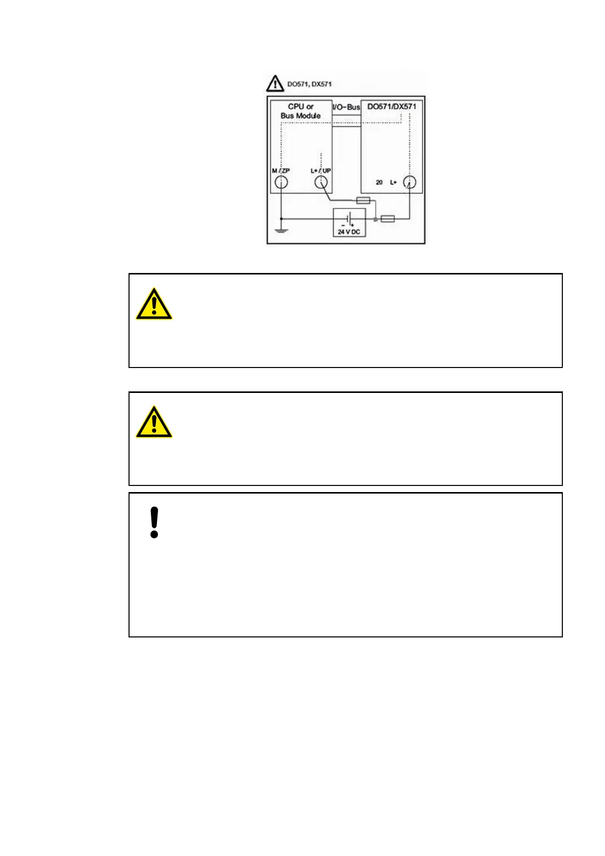
Fig. 26: Power supply - the minus connection is realized via the I/O bus
WARNING!
Risk of death by electric shock!
The terminals of the module can carry 240 V voltage.
Make sure that all voltage sources (supply and process voltage) are switched
off before you begin with operations at the system.
For screw-type terminals only:
WARNING!
For screw terminals only: Danger of death by electric shock!
The IP 20 protection degree is only provided if all terminal screws are tightened.
Tighten all screws of unused load terminals of relay outputs if voltages > 24 V
are connected to the relay group.
NOTICE!
Risk of damaging the I/O Module!
The outputs are not protected against short circuit and overload.
– Never short-circuit or overload the outputs.
– Never connect inductive loads without an external suppression against
voltage peaks due to inductive kickback.
– Never connect voltages > 240 V. All outputs must be supplied from the
same phase.
– Use an external 5 A fast protection fuse for the outputs.
The meaning of the LEDs is described in the Displays section
Ä
Chapter 1.5.1.1.13.7 “State
LEDs” on page 294.
I/O Configuration
The module itself does not store configuration data. It receives its parameterization data from
the master device of the I/O bus (CPU or bus module) during power-up of the system.
Hence, replacing I/O modules is possible without any re-parameterization via software.
I/O Modules > Digital I/O Modules
2019/04/17 3ADR010121, 13, en_US 291