Interface Pin Description
5 NC Not connected
6 Rx- Receive Data -
7 NC Not connected
8 NC Not connected
Shield Cable shield Functional earth
The supported protocols and used Ethernet ports can be found in a separate chapter.
Communication via Modbus TCP/IP is described in detail in a separate chapter.
WARNING!
Risk of death by electric shock!
The terminals of the module can carry 240 V voltage.
Make sure that all voltage sources (supply and process voltage) are switched
off before you begin with operations at the system.
NOTICE!
Risk of damaging the PLC modules!
Overvoltages and short circuits might damage the PLC modules.
– Make sure that all voltage sources (supply and process voltage) are
switched off before you begin with operations at the system.
– Never connect any voltages or signals to reserved terminals (marked with
---). Reserved terminals may carry internal voltages.
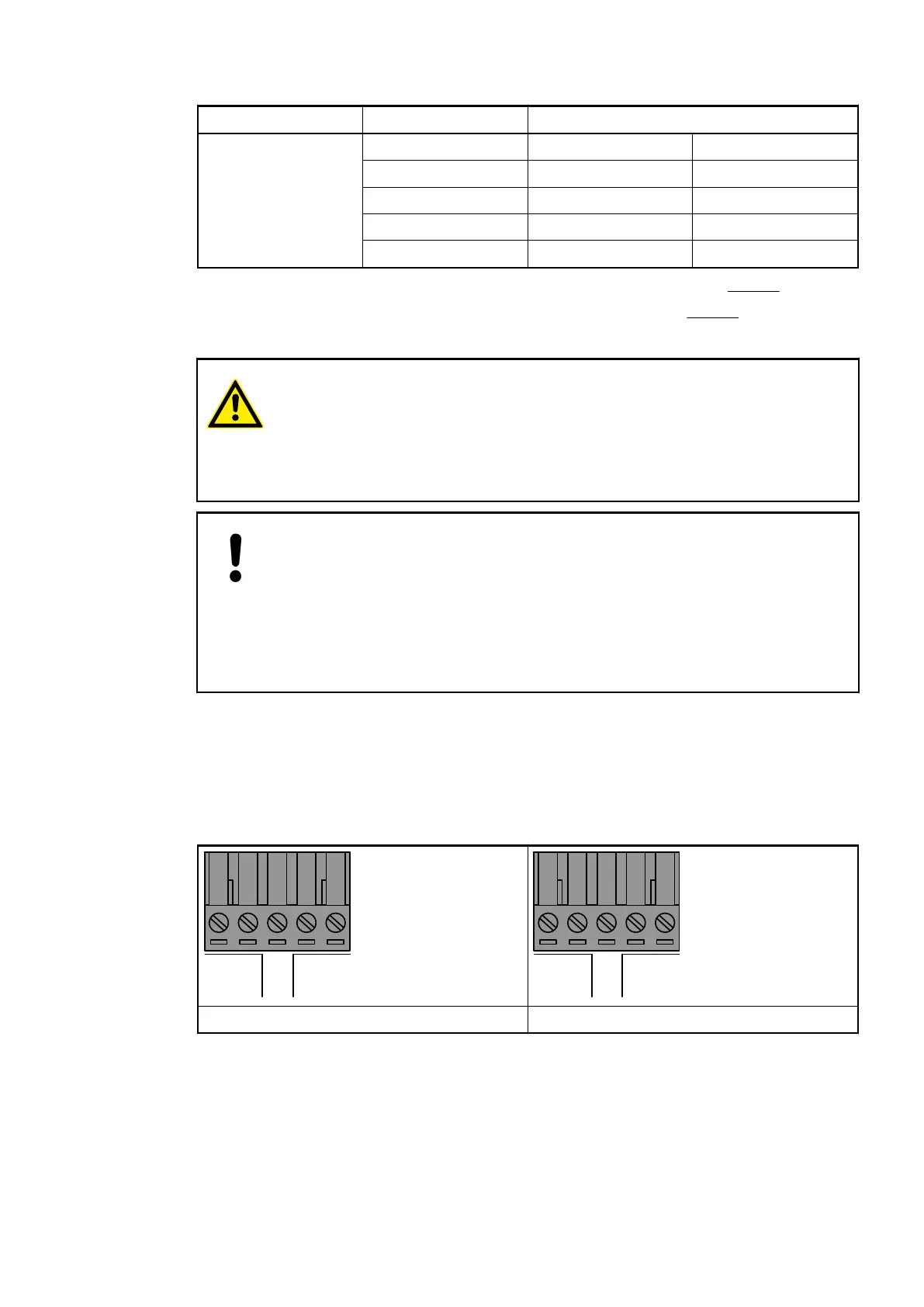
1.2.1.1.4 Power Supply
Depending on the variant, the processor modules can be connected to the following supply vol-
tages:
L+ M F + M
24VDC OUT24VDC IN
LE
L N FE L+ M
24VDC OUT
100−240VAC IN
24 VDC 100 - 240 VAC
The electrical connection is established via a removable 5-pin terminal block. As the terminal
block is also available as a spare part (inside TA570 Spare Part Set for AC500-eCo processor
modules), further information on the terminal block for power supply and the terminal block for
serial RS-485 adaptor is provided under
Ä
Chapter 1.8.1.7 “TA570 - Spare Part Set”
on page 1121.
The 24 VDC variant contains 2 L+ and M terminals. The L+ terminal on the left side is the input
and the right side is the output. The M terminals are internally interconnected. The supply can
be easily looped through to the onboard digital inputs.
Electrical Con-
nection
Power Supply
Processor Modules > AC500-eCo
2019/04/17 3ADR010121, 13, en_US 27