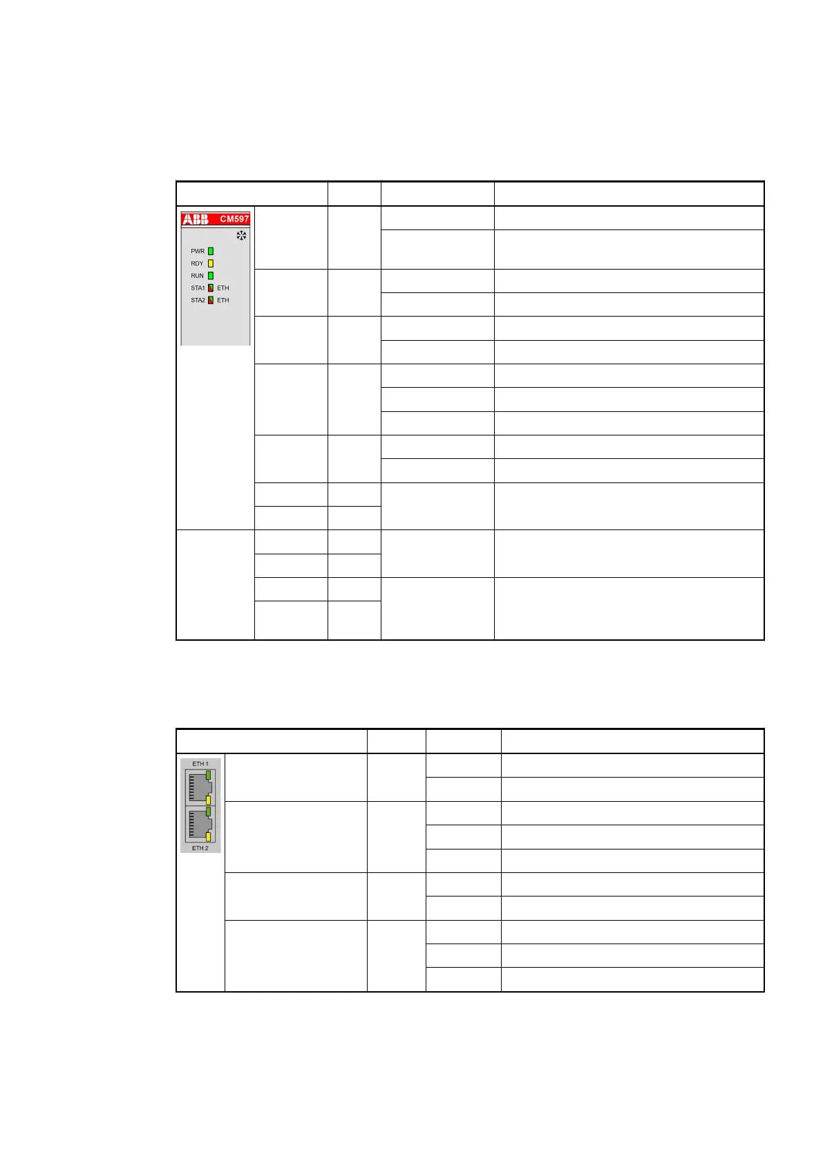
1.3.6.1.3 State LEDs
The Ethernet state is shown by the Ethernet communication module's LEDs.
Table 27: Meaning of the diagnosis LEDs
LED Color State Description
PWR Green On Power supply available
Off Power supply not available or defective
hardware
RDY Yellow On Boot procedure
Blinking Boot failure
RUN Green On Communication module is operational
Off Communication module is not operational
STA1 Green Blinking (1 Hz) Device ready
Blinking (5 Hz) Device configured / UDP traffic
On Modbus communication established
STA2 Red On Modbus communication error
Off No error
STA1 Yellow Blinking
(synchronously)
No production data available,
no bus communication possible.
STA2 Yellow
LED state
during
firmware
update
STA1 Green Blinking
(synchronously)
Firmware file transfers during
communication module firmware update.
STA2 Red
STA1 Green Blinking
(alternately)
Communication module writes the
firmware file to the internal flash.
Do not power off the PLC!
STA2 Red
The RJ45 Ethernet connector contains two LEDs showing the current Ethernet port connection
state.
Table 28: Meaning of the diagnosis LEDs
LED Color State Description
ETH1 LED "Link" Green On Ethernet connection established
Off No Ethernet connection
ETH1 LED "RX/TX" Yellow On ---
Blinking Device sends/receives frames
Off ---
ETH2 LED "Link" Green On Ethernet connection established
Off No Ethernet connection
ETH2 LED "RX/TX" Yellow On ---
Blinking Device sends/receives frames
Off ---
Communication Modules (AC500 Standard) > Ethernet
2019/04/173ADR010121, 13, en_US122