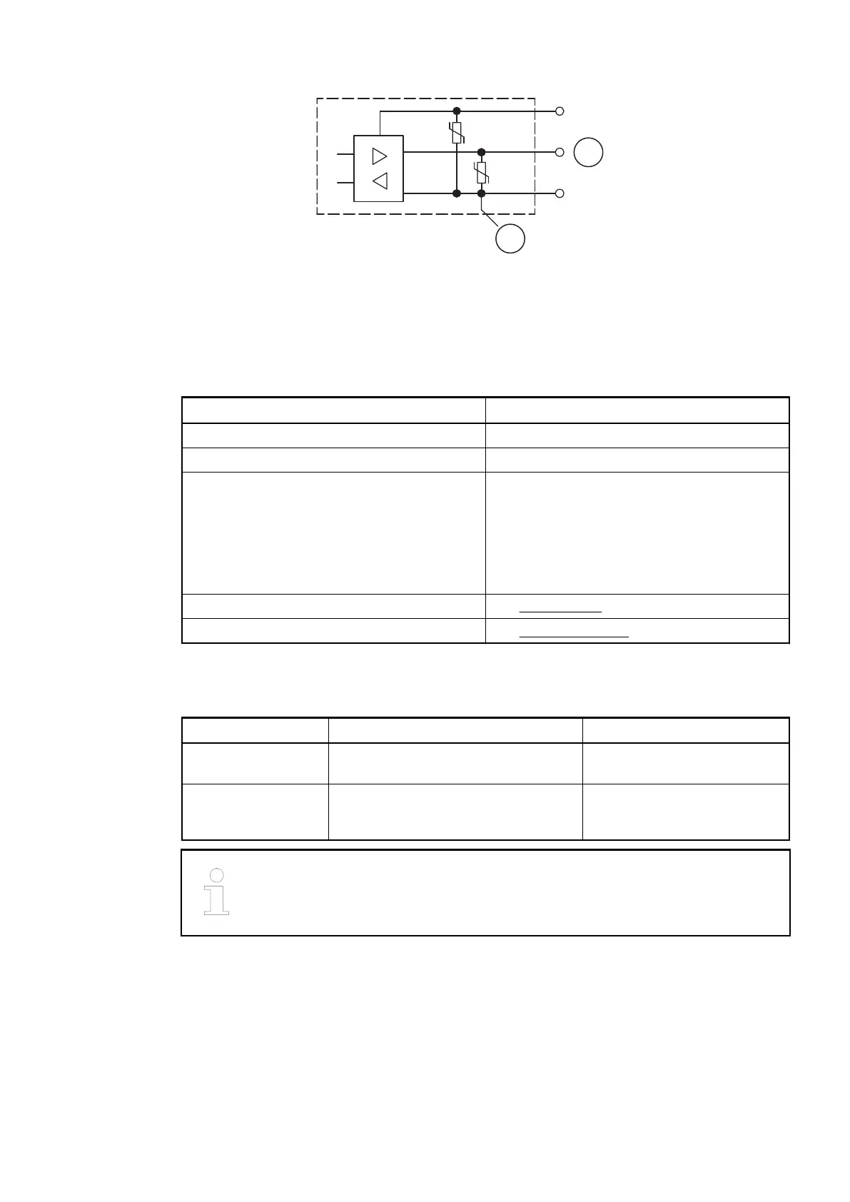
Fig. 190: Digital input/output (circuit diagram)
1 Digital input/output
2 For demagnetization when inductive loads are turned off
Technical Data of the Fast Counter
Parameter Value
Used inputs Terminal 2.0 (DI8),Terminal 2.1 (DI9)
Used outputs Terminal 3.0 (DO8)
Counting frequency Depending on operation mode:
Mode 1- 6: max. 200 kHz
Mode 7: max. 50 kHz
Mode 9: max. 35 kHz
Mode 10: max. 20 kHz
Detailed description See Fast Counter
Operating modes See Operating modes
1.7.4.2.10 Ordering Data
Ordering No. Scope of delivery Product Life Cycle Phase *)
1SAP 222 200
R0001
CI522-MODTCP, Modbus TCP bus
module, 8 DC, 8 DI and 8 DO
Active
1SAP 422 200
R0001
CI522-MODTCP-XC, Modbus TCP
bus module, 8 DC, 8 DI and 8 DO,
XC version
Active
*) For planning and commissioning of new installations use modules in Active
status only.
Communication Interface Modules (S500) > Modbus
2019/04/17 3ADR010121, 13, en_US 941