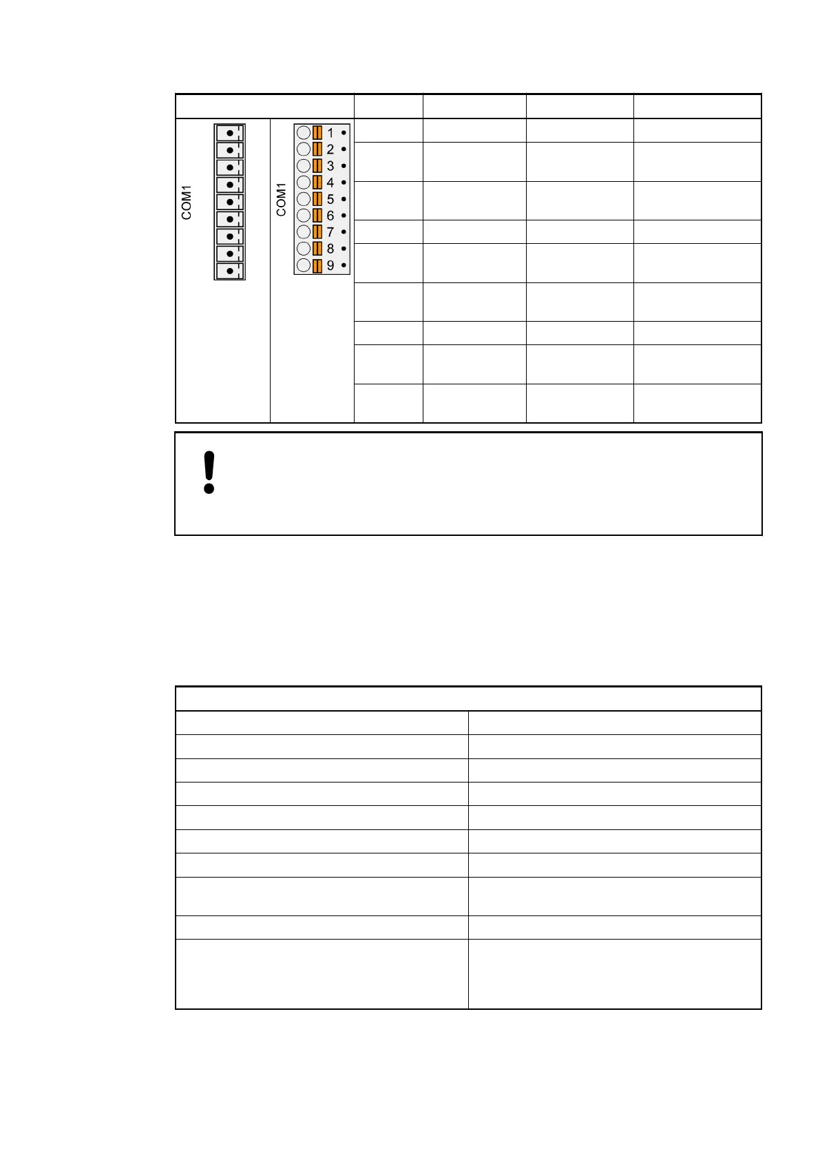
Pin Signal Interface Description
Terminal
block
removed
Terminal
block
inserted
1 Terminator P RS-485 Terminator P
2 RxD/TxD-P RS-485 Receive/Transmit,
positive
3 RxD/TxD-N RS-485 Receive/Transmit,
negative
4 Terminator N RS-485 Terminator N
5 RTS RS-232 Request to send
(output)
6 TxD RS-232 Transmit data
(output)
7 SGND Signal Ground Signal Ground
8 RxD RS-232 Receive data
(input)
9 CTS RS-232 Clear to send
(input)
NOTICE!
Unused connector!
Make sure that the terminal block is always connected to the terminal base,
even if you do not use the interface.
With connecting the terminals 1-2 and 3-4, a pull-up and a pull-down resistor can be activated
(see chapter Serial Interface COM1
Ä
Chapter 2.6.4.6 “Serial Interface COM1 of the Terminal
Bases” on page 1278.
2.6.4.8.2 Wiring
Bus line
Construction 2 cores, twisted, with common shield
Conductor cross section > 0.22 mm² (24 AWG)
Recommendation 0.5 mm² corresponds to 0.8 mm
Twisting rate > 10 per meter (symmetrically twisted)
Core insulation Polyethylene (PE)
Resistance per core < 100 Ω/km
Characteristic impedance ca. 120 Ω (100 Ω...150 Ω)
Capacitance between the cores < 55 nF/km (if higher, the max. bus length
must be reduced)
Terminating resistors 120 Ω ¼ W at both line ends
Remarks Shielded cables with PVC core insulation and
a core diameter of 0.8 mm can be used up to
a length of ca. 50 m. In this case, the bus ter-
minating resistor is ca. 100 Ω.
Remarks:
Pin assignment
Wiring
System Assembly, Construction and Connection
AC500 (Standard) > Connection and Wiring
2019/04/17 3ADR010121, 13, en_US 1283