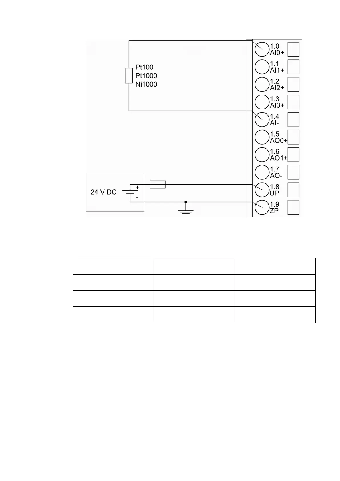
Fig. 176: Connection of resistance thermometers in 2-wire configuration to the analog inputs
The following measuring ranges can be configured
Ä
Chapter 1.7.4.1.7 “Parameterization”
on page 897 and
Ä
Chapter 1.7.4.1.9 “Measuring Ranges” on page 909:
Pt100 -50 °C...+70 °C 2-wire configuration, 1
channel used
Pt100 -50 °C...+400 °C 2-wire configuration, 1
channel used
Pt1000 -50 °C...+400 °C 2-wire configuration, 1
channel used
Ni1000 -50 °C...+150 °C 2-wire configuration, 1
channel used
The function of the LEDs is described under Diagnosis and displays / Displays
Ä
Chapter
1.7.4.1.8 “Diagnosis and State LEDs” on page 903.
The module CI521-MODTCP performs a linearization of the resistance characteristic.
To avoid error messages from unused analog input channels, configure them as "unused".
Connection of Resistance Thermometers in 3-wire Configuration to the Analog Inputs
When resistance thermometers (Pt100, Pt1000, Ni1000) are used, a constant current must flow
through them to build the necessary voltage drop for the evaluation. For this, the module CI521-
MODTCP provides a constant current source which is multiplexed over the max. 4 analog input
channels.
The following figure shows the connection of resistance thermometers in 3-wire configuration to
the analog inputs AI0 and AI1. Proceed with the analog inputs AI2 and AI3 in the same way.
Communication Interface Modules (S500) > Modbus
2019/04/173ADR010121, 13, en_US886